What is an FPGA?

What is FPGA? FPGA stands for Field Programmable Gate Array. Let's analyze the term:

1. Field-Programmable: An FPGA is manufactured to be easily reconfigured by developers, designers or customers. To program an FPGA as a specific configuration, Verilog HDL or VHDL (Hardware Description Language) is used as the standard language for FPGA programming.

2. Gate-Array: An FPGA consists of an array of programmable logic gates/ blocks such as AND, OR, XOR, NOT, memory elements, DSP components, etc., and reconfigurable interconnects which are to connect logic gates together for performing a specific function.

What is FPGA

A complete 8-bit Microcontroller in VHDL

In this VHDL project, VHDL code for a microcontroller is presented. The 8-bit microcontroller is designed, implemented, and operational as a full design which users can program the microcontroller using assembly language. 

The instruction set and architecture of the 8-bit microcontroller are available at Chapter 13 in the book "Introduction to Logic Circuits and Logic Design with VHDL" by prof. Brock J. LaMeres. The microcontroller has an 8-bit processor, a 128-byte program memory, a 96-byte RAM, 16x8-bit output ports, and 16x8-bit input ports. Users can program the microcontroller by inserting opcodes and operands in the program memory.

After completing the design, the microcontroller is implemented on FPGA DE0-nano board as shown in the figure below.

VHDL Code for microcontroller

32-bit Unsigned Divider in Verilog

In this project, a 32-bit unsigned divider is implemented in Verilog using both structural and behavioral models. The Verilog code for the divider is synthesizable and can be implemented on FPGA. 

verilog code for unsigned divider

Fixed-Point Matrix Multiplication in Verilog[Full code+Tutorials]


This Verilog project is to implement a synthesizable fixed point matrix multiplication in Verilog HDL. Full Verilog code for the matrix multiplication is presented.

Two fixed point matrixes A and B are BRAMs created by Xilinx Core Generator. After multiplying these two matrixes, the result is written to another matrix which is BRAM. The testbench code reads the content of the output matrix and writes to a "result.dat" file to check the result.


fixed-point matrix multiplication in Verilog

Verilog License Plate Recognition on FPGA

A plate license recognition system is implemented in Matlab and then it is implemented on FPGA Xilinx Spartan-6 using Verilog. Below is the test environment for the system on FPGA.

Verilog code for License Plate Recognition

Virtual Point Robot in MIPS Assembly

In this project, a MIPS Assembly program is written to move a virtual point robot on a given environment. 

The dimensions of the environment, starting coordinates of the robot, locations of obstacles and moving commands will be provided. The program should move the robot according to the given provided commands, environment dimensions, and obstacle coordinates. At the end of the program, the final coordinate of the robot should be presented. 

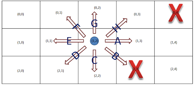
Below is an example of the input : 
3x5#(1,2)#(0,4),(2,3)#ACCAGGGACEEEFFDB#
3x5 is the dimension of the provided environment.
(1,2) is the initial coordinate of the robot.
(0,4) and (2,3) are the coordinates of the obstacles.
# is the character which separates the input parts.

virtual point robot mips
Virtual presentation of the example environment

[Full VHDL code] Matrix Multiplication Design using VHDL

VHDL code for Matrix multiplication is presented. This VHDL project is aimed to develop and implement a synthesizable matrix multiplier core, which is able to perform matrix calculation for matrices with the size of 32x32.

Each component of the matrices is 16-bit unsigned integer. The core is implemented on Xilinx FPGA Spartan-6 XC6SLX45-CSG324-3. Both behavior and post-route verification are completed. The simulated result is accurately compared to Matlab implementation result.

   
VHDL code for matrix multiplication

Verilog Code for Multiplier using Carry-Look-Ahead Adders

This project is to implement a parameterized multiplier using carry-look-ahead adders in Verilog. The Verilog code for the multiplier is provided.

Users can change the number of bits of the multiplier by modifying the predefined parameters. The parameters such as MULTICAND_WID and MULTIPLIER_WID are to define the number of bits of the multiplicand and multiplier, and when we want to change the number of bits, just change these parameters and re-synthesize or simulate.
Verilog code for Multiplier

Verilog code for Microcontroller (Part 3- Verilog code)


In this project, Verilog code for a microcontroller is presented. The microcontroller architecture and instruction set are shown in part 1 and part 2

verilog code for microcontroller

Verilog code for microcontroller (Part-2- Design)

In this post, architecture design for the microcontroller is presented. Verilog code for the microcontroller is posted in part 3.

The following diagram is the architecture of the microcontroller. The datapath is shown as black arrows, and control signals are red arrows.

Verilog code for microcontroller

Verilog code for Microcontroller (Part 1 - Specification)

In this project, Verilog code for a microcontroller is presented. Before implementing, the instruction set architecture for the microcontroller is presented in this part. (Part-2 and Part-3)


Verilog code for microcontroller

Floating point numbers in MIPS Assembly

Floating point numbers in MIPS assembly is presented in this project. 

A lot of FPGA/ Verilog/ VHDL are posted and today I want to post a MIPS assembly project. MIPS is a very common microprocessor being taught in many universities and there are a lot of FPGA/ Verilog/ VHDL projects on implementing MIPS processor based on a provided Instruction set. After the MIPS is implemented, we can program the MIPS by downloading the MIPS assembly code into the instruction memory. 
This is a very simple MIPS Assembly code for students to play with floating point numbers. The simulator being used is Qtspim and for the instruction set of MIPS architecture, you can visit here. Users will enter eight floating point numbers and the program finds the minimum, maximum and average number of the entered floating point numbers.
The output console is as follows:

MIPS Assebmly floating points

N-bit ring counter in VHDL

This VHDL project is to implement a parameterized N-bit switch tail ring counter using VHDL. VHDL code for parameterized ring counter is presented in this project.

It means that users can easily change the number of bits of the ring counter without modifying VHDL code inside the ring counter. There is a parameter N to define the number of bits of the ring counter, and when we want to change the number of bits, just change the parameter N and re-synthesize or simulate. 

VHDL code for ring counter

VHDL code for digital clock on FPGA

This VHDL project is the VHDL version code of the digital clock in Verilog I posted before(link). The VHDL code for the digital clock is synthesizable for FPGA implementation and full VHDL code is provided.

This digital clock is a reconfigurable 24-hour clock displaying hours, minutes, and seconds on seven-segment LEDs (Tutorials on 7-segment LEDs: here). Besides, users can manually set the time of the digital clock including hours and minutes through switches. 
VHDL code for digital  clock on FPGA

Verilog code for 4x4 Multiplier

This project is to implement a 4x4 multiplier using Verilog HDL. Full Verilog code for the multiplier is presented. 

The technique being used is shift/add algorithm, but the different feature is using a two-phase self-clocking system in order to reduce the multiplying time by half.

Verilog code for 4x4 multiplier

Verilog code for Car Parking System

This simple project is to implement a car parking system in Verilog. The Verilog code for the car parking system is fully presented.

In the entrance of the parking system, there is a sensor which is activated to detect a vehicle coming. Once the sensor is triggered, a password is requested to open the gate. If the entered password is correct, the gate would open to let the vehicle get in. Otherwise, the gate is still locked. If the current car is getting in the car park being detected by the exit sensor and another the car comes, the door will be locked and requires the coming car to enter passwords.


verilog code for car parking system

Image processing on FPGA using Verilog HDL

This FPGA project is aimed to show in details how to process an image using Verilog from reading an input bitmap image (.bmp) in Verilog, processing and writing the processed result to an output bitmap image in Verilog. The full Verilog code for reading image, image processing, and writing image is provided.

Image processing on FPGA using Verilog HDL

VHDL code for 8-bit Comparator

VHDL code for a 8-bit comparator is presented in this post. 74F521 is an 8-bit identity comparator which provides the low output if two 8-bit inputs are matched. 

Below are the truth table and symbol of the comparator.

VHDL code for comparator
Truth table

How to load a text file or an image into FPGA

This FPGA tutorial presents two ways to load a text file or an image into FPGA using Verilog or VHDL for image processing. It can be really useful for functional verifications in real-time FPGA image processing projects.


16-bit CPU design in LogiSim

A 16-bit CPU design in Logisim is presented. The 16-bit simple CPU with data-path and control unit is shown as below:

cpu logisim
Figure 1. Block diagram of a 16-bit simple CPU

Verilog code for Traffic light controller

A Verilog source code for a traffic light controller on FPGA is presented. A sensor on the farm is to detect if there are any vehicles and change the traffic light to allow the vehicles to cross the highway. Otherwise, highway light is always green since it has higher priority than the farm. 


Verilog code for Traffic light controller

Verilog code for Alarm clock on FPGA

Verilog code for an alarm clock on FPGA is presented in this project. The Verilog code is fully synthesizable for FPGA implementation. 

The simple alarm clock is shown in the following figure. The alarm clock outputs a real-time clock with a 24-hour format and also provides an alarm feature. Users also can set the clock time through switches. 
Verilog code for Alarm clock on FPGA

Dynamically allocating memory in MIPS Assembly

MIPS Assembly Dynamically Allocating memory example:

Enter player's name, points and minutes, and then sorting using dynamically allocating techniques. 

Expected results:

MIPS assembly dynamically allocating memory

Popular FPGA/Verilog/VHDL Projects