

This VHDL project is the VHDL version code of the digital clock in Verilog I posted before(link). The VHDL code for the digital clock is synthesizable for FPGA implementation and full VHDL code is provided.
This digital clock is a reconfigurable 24-hour clock displaying hours, minutes, and seconds on seven-segment LEDs (Tutorials on 7-segment LEDs: here). Besides, users can manually set the time of the digital clock including hours and minutes through switches.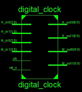
VHDL code for digital clock:
library IEEE;
use IEEE.STD_LOGIC_1164.ALL;
use IEEE.numeric_std.all;
-- fpga4student.com FPGA projects, VHDL projects, Verilog projects
-- VHDL project: VHDL code for digital clock
entity digital_clock is
port (
 clk: in std_logic;
 -- clock 50 MHz
 rst_n: in std_logic;
 -- Active low reset pulse, to set the time to the input hour and minute (as
 -- defined by the H_in1, H_in0, M_in1, and M_in0 inputs) and the second to 00.
 -- For normal operation, this input pin should be 1.
 H_in1: in std_logic_vector(1 downto 0);
 -- 2-bit input used to set the most significant hour digit of the clock
 -- Valid values are 0 to 2.
 H_in0: in std_logic_vector(3 downto 0);
 -- 4-bit input used to set the least significant hour digit of the clock
 -- Valid values are 0 to 9.
 M_in1: in std_logic_vector(3 downto 0);
 -- 4-bit input used to set the most significant minute digit of the clock
 -- Valid values are 0 to 9.
 M_in0: in std_logic_vector(3 downto 0);
 -- 4-bit input used to set the least significant minute digit of the clock
 -- Valid values are 0 to 9.
 H_out1: out std_logic_vector(6 downto 0);
 -- The most significant digit of the hour. Valid values are 0 to 2 ( Hexadecimal value on 7-segment LED)
 H_out0: out std_logic_vector(6 downto 0);
 -- The most significant digit of the hour. Valid values are 0 to 9 ( Hexadecimal value on 7-segment LED)
 M_out1: out std_logic_vector(6 downto 0);
 -- The most significant digit of the minute. Valid values are 0 to 9 ( Hexadecimal value on 7-segment LED)
 M_out0: out std_logic_vector(6 downto 0)
 -- The most significant digit of the minute. Valid values are 0 to 9 ( Hexadecimal value on 7-segment LED)
 );
end digital_clock;
architecture Behavioral of digital_clock is
component bin2hex
port (
 Bin: in std_logic_vector(3 downto 0);
 Hout: out std_logic_vector(6 downto 0)
 );
end component;
component clk_div
port (
 clk_50: in std_logic;
 clk_1s: out std_logic
     );
end component;
-- fpga4student.com FPGA projects, VHDL projects, Verilog projects
signal clk_1s: std_logic; -- 1-s clock
signal counter_hour, counter_minute, counter_second: integer;
-- counter using for create time
signal H_out1_bin: std_logic_vector(3 downto 0); --The most significant digit of the hour
signal H_out0_bin: std_logic_vector(3 downto 0);--The least significant digit of the hour
signal M_out1_bin: std_logic_vector(3 downto 0);--The most significant digit of the minute
signal M_out0_bin: std_logic_vector(3 downto 0);--The least significant digit of the minute
begin
-- create 1-s clock --|
create_1s_clock: clk_div port map (clk_50 => clk, clk_1s => clk_1s);
-- clock operation ---|
process(clk_1s,rst_n) begin
-- fpga4student.com FPGA projects, VHDL projects, Verilog projects
  if(rst_n = '0') then
 counter_hour <= to_integer(unsigned(H_in1))*10 + to_integer(unsigned(H_in0));
 counter_minute <= to_integer(unsigned(M_in1))*10 + to_integer(unsigned(M_in0));
 counter_second <= 0;
 elsif(rising_edge(clk_1s)) then
 counter_second <= counter_second + 1;
 if(counter_second >=59) then -- second > 59 then minute increases
 counter_minute <= counter_minute + 1;
 counter_second <= 0;
 if(counter_minute >=59) then -- minute > 59 then hour increases
 counter_minute <= 0;
 counter_hour <= counter_hour + 1;
 if(counter_hour >= 24) then -- hour > 24 then set hour to 0
 counter_hour <= 0;
 end if;
 end if;
 end if;
 end if;
end process;
----------------------|
-- Conversion time ---|
----------------------|
-- H_out1 binary value
 H_out1_bin <= x"2" when counter_hour >=20 else
 x"1" when counter_hour >=10 else
 x"0";
-- 7-Segment LED display of H_out1
convert_hex_H_out1: bin2hex port map (Bin => H_out1_bin, Hout => H_out1);
-- H_out0 binary value
 H_out0_bin <= std_logic_vector(to_unsigned((counter_hour - to_integer(unsigned(H_out1_bin))*10),4));
-- 7-Segment LED display of H_out0
convert_hex_H_out0: bin2hex port map (Bin => H_out0_bin, Hout => H_out0);
-- M_out1 binary value
 M_out1_bin <= x"5" when counter_minute >=50 else
 x"4" when counter_minute >=40 else
 x"3" when counter_minute >=30 else
 x"2" when counter_minute >=20 else
 x"1" when counter_minute >=10 else
 x"0";
-- 7-Segment LED display of M_out1
convert_hex_M_out1: bin2hex port map (Bin => M_out1_bin, Hout => M_out1);
-- M_out0 binary value
 M_out0_bin <= std_logic_vector(to_unsigned((counter_minute - to_integer(unsigned(M_out1_bin))*10),4));
-- 7-Segment LED display of M_out0
convert_hex_M_out0: bin2hex port map (Bin => M_out0_bin, Hout => M_out0);
end Behavioral;
-- fpga4student.com FPGA projects, VHDL projects, Verilog projects
-- VHDL project: VHDL code for digital clock
-- BCD to HEX For 7-segment LEDs display
library IEEE;
use IEEE.STD_LOGIC_1164.ALL;
entity bin2hex is
port (
 Bin: in std_logic_vector(3 downto 0);
 Hout: out std_logic_vector(6 downto 0)
);
end bin2hex;
architecture Behavioral of bin2hex is
begin
 process(Bin)
 begin
  case(Bin) is
   when "0000" =>  Hout <= "1000000"; --0--
   when "0001" =>  Hout <= "1111001"; --1--
   when "0010" =>  Hout <= "0100100"; --2--
   when "0011" =>  Hout <= "0110000"; --3--
   when "0100" =>  Hout <= "0011001"; --4--
   when "0101" =>  Hout <= "0010010"; --5--
   when "0110" =>  Hout <= "0000010"; --6--
   when "0111" =>  Hout <= "1111000"; --7--
   when "1000" =>  Hout <= "0000000"; --8--
   when "1001" =>  Hout <= "0010000"; --9--
   when "1010" =>  Hout <= "0001000"; --a--
   when "1011" =>  Hout <= "0000011"; --b--
   when "1100" =>  Hout <= "1000110"; --c--
   when "1101" =>  Hout <= "0100001"; --d--
   when "1110" =>  Hout <= "0000110"; --e--
   when others =>  Hout <= "0001110";
   end case;
 end process;
end Behavioral;
-- fpga4student.com FPGA projects, VHDL projects, Verilog projects
-- VHDL project: VHDL code for digital clock
-- Clock divider module to get 1 second clock
library IEEE;
use IEEE.STD_LOGIC_1164.ALL;
USE IEEE.STD_LOGIC_UNSIGNED.ALL;
entity clk_div is
port (
   clk_50: in std_logic;
   clk_1s: out std_logic
  );
end clk_div;
architecture Behavioral of clk_div is
signal counter: std_logic_vector(27 downto 0):=(others =>'0');
begin
 process(clk_50)
 begin
  if(rising_edge(clk_50)) then
   counter <= counter + x"0000001";
   if(counter>=x"2FAF080") then -- for running on FPGA -- comment when running simulation
   --if(counter_slow>=x"0000001") then -- for running simulation -- comment when running on FPGA
    counter <= x"0000000";
   end if;
  end if;
 end process;
 clk_1s <= '0' when counter < x"17D7840" else '1';
end Behavioral;
Testbench VHDL code for digital clock:
LIBRARY ieee;
USE ieee.std_logic_1164.ALL;
-- fpga4student.com FPGA projects, VHDL projects, Verilog projects
-- VHDL project: VHDL code for digital clock
ENTITY tb_digital_clock IS
END tb_digital_clock;
ARCHITECTURE behavior OF tb_digital_clock IS
  -- Component Declaration for the Unit Under Test (UUT)
-- fpga4student.com FPGA projects, VHDL projects, Verilog projects
    COMPONENT digital_clock
    PORT(
         clk : IN  std_logic;
         rst_n : IN  std_logic;
         H_in1 : IN  std_logic_vector(1 downto 0);
         H_in0 : IN  std_logic_vector(3 downto 0);
         M_in1 : IN  std_logic_vector(3 downto 0);
         M_in0 : IN  std_logic_vector(3 downto 0);
         H_out1 : OUT  std_logic_vector(6 downto 0);
         H_out0 : OUT  std_logic_vector(6 downto 0);
         M_out1 : OUT  std_logic_vector(6 downto 0);
         M_out0 : OUT  std_logic_vector(6 downto 0)
        );
    END COMPONENT;
   --Inputs
   signal clk : std_logic := '0';
   signal rst_n : std_logic := '0';
   signal H_in1 : std_logic_vector(1 downto 0) := (others => '0');
   signal H_in0 : std_logic_vector(3 downto 0) := (others => '0');
   signal M_in1 : std_logic_vector(3 downto 0) := (others => '0');
   signal M_in0 : std_logic_vector(3 downto 0) := (others => '0');

  --Outputs
   signal H_out1 : std_logic_vector(6 downto 0);
   signal H_out0 : std_logic_vector(6 downto 0);
   signal M_out1 : std_logic_vector(6 downto 0);
   signal M_out0 : std_logic_vector(6 downto 0);
   -- Clock period definitions
   constant clk_period : time := 10 ps;
BEGIN
-- fpga4student.com FPGA projects, VHDL projects, Verilog projects
 -- Instantiate the Unit Under Test (UUT)
   uut: digital_clock PORT MAP (
          clk => clk,
          rst_n => rst_n,
          H_in1 => H_in1,
          H_in0 => H_in0,
          M_in1 => M_in1,
          M_in0 => M_in0,
          H_out1 => H_out1,
          H_out0 => H_out0,
          M_out1 => M_out1,
          M_out0 => M_out0
        );
   -- Clock process definitions
   clk_process :process
   begin
 clk <= '0';
 wait for clk_period/2;
 clk <= '1';
 wait for clk_period/2;
   end process;
   -- Stimulus process
   stim_proc: process
   begin
      -- hold reset state for 100 ns.
 rst_n <= '0';
 H_in1 <= "01";
 H_in0 <= x"0";
 M_in1 <= x"2";
 M_in0 <= x"0";
      wait for 100 ns;
 rst_n <= '1';
      wait for clk_period*10;
-- insert stimulus here
-- fpga4student.com FPGA projects, VHDL projects, Verilog projects
      wait;
   end process;

END;
Simulation results for the digital clock in VHDL:
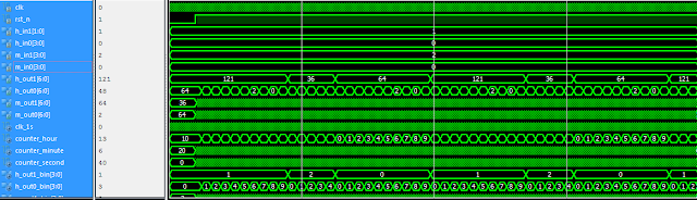
It is noted that when you run the simulation, you should use direct clock from input to simulate instead of the 1-second clock or reduce the value of the divisor in the clk_div entity because it would take a long time to create the 1-second clock.
What is FPGA Programming? FPGA vs Software programming
Recommended and affordable Xilinx FPGA boards for students
Recommended and affordable Altera FPGA boards for students
Recommended VHDL projects:
1. What is an FPGA? How VHDL works on FPGA
2. VHDL code for FIFO memory
3. VHDL code for FIR Filter
4. VHDL code for 8-bit Microcontroller
5. VHDL code for Matrix Multiplication
6. VHDL code for Switch Tail Ring Counter
7. VHDL code for digital alarm clock on FPGA
8. VHDL code for 8-bit Comparator
9. How to load a text file into FPGA using VHDL
10. VHDL code for D Flip Flop
11. VHDL code for Full Adder
12. PWM Generator in VHDL with Variable Duty Cycle
13. VHDL code for ALU
14. VHDL code for counters with testbench
15. VHDL code for 16-bit ALU
16. Shifter Design in VHDL
17. Non-linear Lookup Table Implementation in VHDL
18. Cryptographic Coprocessor Design in VHDL
19. Verilog vs VHDL: Explain by Examples
20. VHDL Code for Clock Divider on FPGA
21. How to generate a clock enable signal instead of creating another clock domain
22. VHDL code for debouncing buttons on FPGA
23. VHDL code for Traffic light controller
24. VHDL code for a simple 2-bit comparator
25. VHDL code for a single-port RAM
22. VHDL code for debouncing buttons on FPGA
23. VHDL code for Traffic light controller
24. VHDL code for a simple 2-bit comparator
25. VHDL code for a single-port RAM
26. VHDL code for Car Parking System using FSM
27. VHDL coding vs Software Programming


nice and good project
ReplyDeleteKindly keep up to date with FPGA projects using Verilog/ VHDL fpga4student.com. Thanks
DeleteI am having an error of : quartus design library work does not contain primary unit "clock_div"! Can anyone help?
ReplyDeleteUpdated full VHDL code for the digital clock
Deleteit is a clock divider to get 1-second clock from 50MHz clock
ReplyDeletecan i get truth tables and k maps for this project?
ReplyDeleteSorry, I don't have truth tables or K map for you.
Deletehow to run this program? and can we have many entity inside one source code
ReplyDeletehow can i know assignments pins? please help
ReplyDeleteWe dont have it. Just assign the IO ports to necessary IOs on your FPGA board.
DeleteCan you please upload the constraints file as well
ReplyDeleteHi, I would be very grateful if someone could help me. The code compiles with no error but when i simulate it the simulation resets after the digital clock reaches 05:06.
ReplyDeleteHow to make digital IC tester using vhdl and fpga
ReplyDeleteI want digital alaram clock displaying in lcd display code
ReplyDelete