

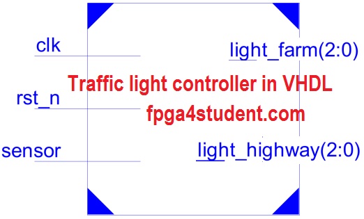
A VHDL code for a traffic light controller on FPGA is presented. The traffic light controller in VHDL is used for an intersection between highway and farm way.
There is a sensor in the farm way side to detect if there is any vehicle on the farm way. If vehicles are detected on the farm way, traffic light on the high way turns to YELLOW, then RED so that the vehicles from the farm way can cross the high way. Otherwise, the traffic light on the high way is always GREEN and traffic light on the farm way is always RED. The time period is 3 seconds for the YELLOW light and 10 seconds for the RED light.
VHDL code for traffic light controller:
-- fpga4student.com FPGA projects, VHDL projects, Verilog projects
-- VHDL project: VHDL code for traffic light controller
library IEEE;
use IEEE.STD_LOGIC_1164.ALL;
use IEEE.STD_LOGIC_UNSIGNED.ALL;
-- Traffic ligh system for a intersection between highway and farm way
-- There is a sensor on the farm way side, when there are vehicles,
-- Traffic light turns to YELLOW, then GREEN to let the vehicles cross the highway
-- Otherwise, always green light on Highway and Red light on farm way
entity traffic_light_controller is
 port ( sensor  : in STD_LOGIC; -- Sensor
        clk  : in STD_LOGIC; -- clock
        rst_n: in STD_LOGIC; -- reset active low
        light_highway  : out STD_LOGIC_VECTOR(2 downto 0); -- light outputs of high way
     light_farm:    out STD_LOGIC_VECTOR(2 downto 0)-- light outputs of farm way
     --RED_YELLOW_GREEN
   );
end traffic_light_controller;
architecture traffic_light of traffic_light_controller is
signal counter_1s: std_logic_vector(27 downto 0):= x"0000000";
signal delay_count:std_logic_vector(3 downto 0):= x"0";
signal delay_10s, delay_3s_F,delay_3s_H, RED_LIGHT_ENABLE, YELLOW_LIGHT1_ENABLE,YELLOW_LIGHT2_ENABLE: std_logic:='0';
signal clk_1s_enable: std_logic; -- 1s clock enable
type FSM_States is (HGRE_FRED, HYEL_FRED, HRED_FGRE, HRED_FYEL);
-- HGRE_FRED : Highway green and farm red
-- HYEL_FRED : Highway yellow and farm red
-- HRED_FGRE : Highway red and farm green
-- HRED_FYEL : Highway red and farm yellow
signal current_state, next_state: FSM_States;
begin
-- next state FSM sequential logic
process(clk,rst_n)
begin
if(rst_n='0') then
 current_state <= HGRE_FRED;
elsif(rising_edge(clk)) then
 current_state <= next_state;
end if;
end process;
-- FSM combinational logic
process(current_state,sensor,delay_3s_F,delay_3s_H,delay_10s)
begin
case current_state is
when HGRE_FRED => -- When Green light on Highway and Red light on Farm way
 RED_LIGHT_ENABLE <= '0';-- disable RED light delay counting
 YELLOW_LIGHT1_ENABLE <= '0';-- disable YELLOW light Highway delay counting
 YELLOW_LIGHT2_ENABLE <= '0';-- disable YELLOW light Farmway delay counting
 light_highway <= "001"; -- Green light on Highway
 light_farm <= "100"; -- Red light on Farm way
 if(sensor = '1') then -- if vehicle is detected on farm way by sensors
  next_state <= HYEL_FRED;
  -- High way turns to Yellow light
 else
  next_state <= HGRE_FRED;
  -- Otherwise, remains GREEN ON highway and RED on Farm way
 end if;
when HYEL_FRED => -- When Yellow light on Highway and Red light on Farm way
 light_highway <= "010";-- Yellow light on Highway
 light_farm <= "100";-- Red light on Farm way
 RED_LIGHT_ENABLE <= '0';-- disable RED light delay counting
 YELLOW_LIGHT1_ENABLE <= '1';-- enable YELLOW light Highway delay counting
 YELLOW_LIGHT2_ENABLE <= '0';-- disable YELLOW light Farmway delay counting
 if(delay_3s_H='1') then
 -- if Yellow light delay counts to 3s,
 -- turn Highway to RED,
 -- Farm way to green light
  next_state <= HRED_FGRE;
 else
  next_state <= HYEL_FRED;
  -- Remains Yellow on highway and Red on Farm way
  -- if Yellow light not yet in 3s
 end if;
when HRED_FGRE =>
 light_highway <= "100";-- RED light on Highway
 light_farm <= "001";-- GREEN light on Farm way
 RED_LIGHT_ENABLE <= '1';-- enable RED light delay counting
 YELLOW_LIGHT1_ENABLE <= '0';-- disable YELLOW light Highway delay counting
 YELLOW_LIGHT2_ENABLE <= '0';-- disable YELLOW light Farmway delay counting
 if(delay_10s='1') then
 -- if RED light on highway is 10s, Farm way turns to Yellow
  next_state <= HRED_FYEL;
 else
  next_state <= HRED_FGRE;
  -- Remains if delay counts for RED light on highway not enough 10s
 end if;
when HRED_FYEL =>
 light_highway <= "100";-- RED light on Highway
 light_farm <= "010";-- Yellow light on Farm way
 RED_LIGHT_ENABLE <= '0'; -- disable RED light delay counting
 YELLOW_LIGHT1_ENABLE <= '0';-- disable YELLOW light Highway delay counting
 YELLOW_LIGHT2_ENABLE <= '1';-- enable YELLOW light Farmway delay counting
 if(delay_3s_F='1') then
 -- if delay for Yellow light is 3s,
 -- turn highway to GREEN light
 -- Farm way to RED Light
 next_state <= HGRE_FRED;
 else
 next_state <= HRED_FYEL;
 -- if not enough 3s, remain the same state
 end if;
when others => next_state <= HGRE_FRED; -- Green on highway, red on farm way
end case;
end process;
-- Delay counts for Yellow and RED light
process(clk)
begin
if(rising_edge(clk)) then
if(clk_1s_enable='1') then
 if(RED_LIGHT_ENABLE='1' or YELLOW_LIGHT1_ENABLE='1' or YELLOW_LIGHT2_ENABLE='1') then
  delay_count <= delay_count + x"1";
  if((delay_count = x"9") and RED_LIGHT_ENABLE ='1') then
   delay_10s <= '1';
   delay_3s_H <= '0';
   delay_3s_F <= '0';
   delay_count <= x"0";
  elsif((delay_count = x"2") and YELLOW_LIGHT1_ENABLE= '1') then
   delay_10s <= '0';
   delay_3s_H <= '1';
   delay_3s_F <= '0';
   delay_count <= x"0";
  elsif((delay_count = x"2") and YELLOW_LIGHT2_ENABLE= '1') then
   delay_10s <= '0';
   delay_3s_H <= '0';
   delay_3s_F <= '1';
   delay_count <= x"0";
  else
   delay_10s <= '0';
   delay_3s_H <= '0';
   delay_3s_F <= '0';
  end if;
 end if;
 end if;
end if;
end process;
-- create delay 1s
process(clk)
begin
if(rising_edge(clk)) then
 counter_1s <= counter_1s + x"0000001";
 if(counter_1s >= x"0000003") then -- x"0004" is for simulation
 -- change to x"2FAF080" for 50 MHz clock running real FPGA
  counter_1s <= x"0000000";
 end if;
end if;
end process;
clk_1s_enable <= '1' when counter_1s = x"0003" else '0'; -- x"0002" is for simulation
-- x"2FAF080" for 50Mhz clock on FPGA
end traffic_light;
VHDL Testbench code for traffic light controller:
-- fpga4student.com FPGA projects, VHDL projects, Verilog projects
-- VHDL project: VHDL code for traffic light controller
LIBRARY ieee;
USE ieee.std_logic_1164.ALL;
-- Testbench VHDL code for traffic light controller
ENTITY tb_traffic_light_controller IS
END tb_traffic_light_controller;

ARCHITECTURE behavior OF tb_traffic_light_controller IS
    -- Component Declaration for the traffic light controller
    COMPONENT traffic_light_controller
    PORT(
         sensor : IN  std_logic;
         clk : IN  std_logic;
         rst_n : IN  std_logic;
         light_highway : OUT  std_logic_vector(2 downto 0);
         light_farm : OUT  std_logic_vector(2 downto 0)
        );
    END COMPONENT;
   signal sensor : std_logic := '0';
   signal clk : std_logic := '0';
   signal rst_n : std_logic := '0';
  --Outputs
   signal light_highway : std_logic_vector(2 downto 0);
   signal light_farm : std_logic_vector(2 downto 0);
   constant clk_period : time := 10 ns;
BEGIN
 -- Instantiate the traffic light controller
   trafficlightcontroller : traffic_light_controller PORT MAP (
          sensor => sensor,
          clk => clk,
          rst_n => rst_n,
          light_highway => light_highway,
          light_farm => light_farm
        );
   -- Clock process definitions
   clk_process :process
   begin
  clk <= '0';
  wait for clk_period/2;
  clk <= '1';
  wait for clk_period/2;
   end process;
   stim_proc: process
   begin
  rst_n <= '0';
  sensor <= '0';
      wait for clk_period*10;
  rst_n <= '1';
  wait for clk_period*20;
  sensor <= '1';
  wait for clk_period*100;
  sensor <= '0';
      wait;
   end process;

END;
Simulation waveform for the traffic light controller in VHDL:

Verilog code for Traffic light controller: here
Recommended VHDL projects:
1. What is an FPGA? How VHDL works on FPGA
2. VHDL code for FIFO memory
3. VHDL code for FIR Filter
4. VHDL code for 8-bit Microcontroller
5. VHDL code for Matrix Multiplication
6. VHDL code for Switch Tail Ring Counter
7. VHDL code for digital alarm clock on FPGA
8. VHDL code for 8-bit Comparator
9. How to load a text file into FPGA using VHDL
10. VHDL code for D Flip Flop
11. VHDL code for Full Adder
12. PWM Generator in VHDL with Variable Duty Cycle
13. VHDL code for ALU
14. VHDL code for counters with testbench
15. VHDL code for 16-bit ALU
16. Shifter Design in VHDL
17. Non-linear Lookup Table Implementation in VHDL
18. Cryptographic Coprocessor Design in VHDL


Hello. I have tried this code using the 50 MHZ clock (Y1) but it couldn't work. Can u help me solve this ? Many Thanks
ReplyDeleteDid you synthesize the code? What did the tool say after synthesis? Was the timing met?
DeleteHi.I have the same problem .Can you help me solve this problem
ReplyDeleteDid you change the clock divisor as mentioned in the code when 50Mhz clock is used?
DeleteHi sir.Can you help me to display delay in seven-segment from this program
ReplyDeletehi! How can I use a segment7 to show the time left for RED light and GREEN light in the vhdl code? Can u help me?
ReplyDeleteHello,
ReplyDeleteHow could you write this same code without using "after" , "wait for" or state machines?
I think I can do it with counters, using processes, but I don't know how...
Hello,
ReplyDeletehow could you write this same code without using "after" , "wait for", or state machines?
I think I can use counters, using processes, but I don't know how...
which type of fpga you used here?
ReplyDeletewhich type of fpga used here?
ReplyDeleteYou can use any FPGA to run this simple project.
DeleteThis project for 2way traffic light or 4way??
ReplyDeletePLEASE! I NEED YOUR HELP. CAN YOU UPLOAD THE Pin assignment constraint file for Basys 3?
ReplyDeleteI am new to VHDL coding but
ReplyDeleteCould you use only one yellow_light_enable?
Rather than using two that do the same thing?
it's up to you. Do whatever you want as long as simulation works.
Deletehello sir,can u put a detailed explanation of this code
ReplyDeleteHow do we put this code into the FPGA Hardware?
ReplyDeleteHi, what are the electronic materials needed in order to create this project? Thankss!
ReplyDelete