

Pulse Width Modulation (PWM) is a very popular modulation technique which is mainly used to control the power delivered to electrical devices such as motors.
This VHDL project presents a simple VHDL code for PWM Generator with Variable Duty Cycle. The VHDL code for PWM Generator is simulated and verified on Xilinx ISIM.

VHDL code for PWM Generator with Variable Duty Cycle:
-- fpga4student.com: FPGA Projects, Verilog projects, VHDL projects
-- VHDL code for PWM Generator
-- Two de-bounced push-buttons
-- One: increase duty cycle by 10%
-- Another: Decrease duty cycle by 10%
library IEEE;
use IEEE.STD_LOGIC_1164.ALL;
USE IEEE.STD_LOGIC_UNSIGNED.ALL;

entity PWM_Generator is
port (
   clk: in std_logic; -- 100MHz clock input
   DUTY_INCREASE: in std_logic; -- button to increase duty cycle by 10%
   DUTY_DECREASE: in std_logic; -- button to decrease duty cycle by 10%
   PWM_OUT: out std_logic -- PWM signal out with frequency of 10MHz
  );
end PWM_Generator;

architecture Behavioral of PWM_Generator is
 -- D-Flip-Flop for debouncing module
 component DFF_Debounce
 Port (
  CLK : in std_logic;
  en : in std_logic;
  D : in std_logic;
  Q : out std_logic
  );
 end component;
 signal slow_clk_en: std_logic:='0'; -- slow clock enable for debouncing
 signal counter_slow: std_logic_vector(27 downto 0):=(others => '0');-- counter for creating slow clock
 signal tmp1,tmp2,duty_inc: std_logic;-- temporary signals for deboucing
 signal tmp3,tmp4,duty_dec: std_logic;-- temporary signals for deboucing
 signal counter_PWM: std_logic_vector(3 downto 0):=(others => '0');-- counter for PWM signal
 signal DUTY_CYCLE: std_logic_vector(3 downto 0):=x"5";
begin
 -- Debouncing process
 -- First generate slow clock enable for deboucing (4Hz)
 process(clk)
 begin
  if(rising_edge(clk)) then
   counter_slow <= counter_slow + x"0000001";
   --if(counter_slow>=x"17D7840") then -- for running on FPGA -- comment when running simulation
   if(counter_slow>=x"0000001") then -- for running simulation -- comment when running on FPGA
    counter_slow <= x"0000000";
   end if;
  end if;
 end process;
 --slow_clk_en <= '1' when counter_slow = x"17D7840" else '0';-- for running on FPGA -- comment when running simulation
 slow_clk_en <= '1' when counter_slow = x"000001" else '0';-- for running simulation -- comment when running on FPGA
 -- debounce part for duty increasing button
 stage0: DFF_Debounce port map(clk,slow_clk_en , DUTY_INCREASE, tmp1);
 stage1: DFF_Debounce port map(clk,slow_clk_en , tmp1, tmp2);
 duty_inc <=  tmp1 and (not tmp2) and slow_clk_en;
 -- debounce part for duty decreasing button
 stage2: DFF_Debounce port map(clk,slow_clk_en , DUTY_DECREASE, tmp3);
 stage3: DFF_Debounce port map(clk,slow_clk_en , tmp3, tmp4);
 duty_dec <=  tmp3 and (not tmp4) and slow_clk_en;
 -- for controlling duty cycle by these buttons
 process(clk)
 begin
  if(rising_edge(clk)) then
   if(duty_inc='1' and DUTY_CYCLE <= x"9") then
    DUTY_CYCLE <= DUTY_CYCLE + x"1";--increase duty cycle by 10%
   elsif(duty_dec='1' and DUTY_CYCLE>=x"1") then
    DUTY_CYCLE <= DUTY_CYCLE - x"1";--decrease duty cycle by 10%
   end if;
  end if;
 end process;
 -- Create 10MHz PWM signal
 process(clk)
 begin
  if(rising_edge(clk)) then
   counter_PWM <= counter_PWM + x"1";
   if(counter_PWM>=x"9") then
    counter_PWM <= x"0";
   end if;
  end if;
 end process;
 PWM_OUT <= '1' when counter_PWM < DUTY_CYCLE else '0';
end Behavioral;

library IEEE;
use IEEE.STD_LOGIC_1164.ALL;

-- fpga4student.com: FPGA Projects, Verilog projects, VHDL projects
-- VHDL code for D Flip Flop
-- D-Flip-Flop for debouncing module
entity DFF_Debounce is
Port (
 CLK : in std_logic;
 en: in std_logic;
 D : in std_logic;
 Q : out std_logic
 );
end DFF_Debounce;
architecture Behavioral of DFF_Debounce is
begin
process(CLK)
begin
 if (rising_edge(CLK)) then
 if (en='1') then
  Q <= D;
 end if;
end if;
end process;
end Behavioral;
VHDL Testbench code for the PWM Generator with Variable Duty Cycle:
-- fpga4student.com: FPGA Projects, Verilog projects, VHDL projects
-- VHDL testbench code for PWM Generator
LIBRARY ieee;
USE ieee.std_logic_1164.ALL;

-- Uncomment the following library declaration if using
-- arithmetic functions with Signed or Unsigned values
--USE ieee.numeric_std.ALL;

ENTITY tb_PWM_Genenrator IS
END tb_PWM_Genenrator;

ARCHITECTURE behavior OF tb_PWM_Genenrator IS

    -- Component Declaration for the Unit Under Test (UUT)

    COMPONENT PWM_Generator
    PORT(
         clk : IN  std_logic;
         DUTY_INCREASE : IN  std_logic;
         DUTY_DECREASE : IN  std_logic;
         PWM_OUT : OUT  std_logic
        );
    END COMPONENT;


   --Inputs
   signal clk : std_logic := '0';
   signal DUTY_INCREASE : std_logic := '0';
   signal DUTY_DECREASE : std_logic := '0';

  --Outputs
   signal PWM_OUT : std_logic;

   -- Clock period definitions
   constant clk_period : time := 10 ns;

BEGIN

 -- Instantiate the Unit Under Test (UUT)
   uut: PWM_Generator PORT MAP (
          clk => clk,
          DUTY_INCREASE => DUTY_INCREASE,
          DUTY_DECREASE => DUTY_DECREASE,
          PWM_OUT => PWM_OUT
        );

   -- Clock process definitions
   clk_process :process
   begin
  clk <= '0';
  wait for clk_period/2;
  clk <= '1';
  wait for clk_period/2;
   end process;


   -- Stimulus process
   stim_proc: process
   begin
  DUTY_INCREASE <= '0';
  DUTY_DECREASE <= '0';
      wait for clk_period*10;
  DUTY_INCREASE <= '1';
      wait for clk_period*10;
  DUTY_INCREASE <= '0';
      wait for clk_period*10;
  DUTY_INCREASE <= '1';
      wait for clk_period*10;
  DUTY_INCREASE <= '0';
      wait for clk_period*10;
  DUTY_INCREASE <= '1';
      wait for clk_period*10;
  DUTY_INCREASE <= '0';
      wait for clk_period*10;
  DUTY_DECREASE <= '1';
      wait for clk_period*10;
  DUTY_DECREASE <= '0';
      wait for clk_period*10;
  DUTY_DECREASE <= '1';
      wait for clk_period*10;
  DUTY_DECREASE <= '0';
      wait for clk_period*10;
  DUTY_DECREASE <= '1';
      wait for clk_period*10;
  DUTY_DECREASE <= '0';
      wait for clk_period*10;

      -- insert stimulus here

      wait;
   end process;

END;
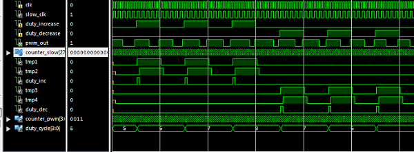
Simulation results for the PWM Generator in VHDL:
Recommended VHDL projects:
1. What is an FPGA? How VHDL works on FPGA
2. VHDL code for FIFO memory
3. VHDL code for FIR Filter
4. VHDL code for 8-bit Microcontroller
5. VHDL code for Matrix Multiplication
6. VHDL code for Switch Tail Ring Counter
7. VHDL code for digital alarm clock on FPGA
8. VHDL code for 8-bit Comparator
9. How to load a text file into FPGA using VHDL
10. VHDL code for D Flip Flop
11. VHDL code for Full Adder
12. PWM Generator in VHDL with Variable Duty Cycle
13. VHDL code for ALU
14. VHDL code for counters with testbench
15. VHDL code for 16-bit ALU
16. Shifter Design in VHDL
17. Non-linear Lookup Table Implementation in VHDL
18. Cryptographic Coprocessor Design in VHDL
19. Verilog vs VHDL: Explain by Examples
20. VHDL Code for Clock Divider on FPGA
21. How to generate a clock enable signal instead of creating another clock domain
22. VHDL code for debouncing buttons on FPGA
23. VHDL code for Traffic light controller
24. VHDL code for a simple 2-bit comparator
25. VHDL code for a single-port RAM
22. VHDL code for debouncing buttons on FPGA
23. VHDL code for Traffic light controller
24. VHDL code for a simple 2-bit comparator
25. VHDL code for a single-port RAM
26. VHDL code for Car Parking System using FSM
27. VHDL coding vs Software Programming


Can you please provide three phase pwm vhdl code.
ReplyDeleteProvide three phase pwm pulse code
ReplyDeleteWhich board are you using? What is the clock rate? Nice work.
ReplyDelete