

A Verilog code for a 4-bit Ripple-Carry Adder is provided in this project.
The 4-bit ripple-carry adder is built using 4 1-bit full adders as shown in the following figure.

You can find the behavioral Verilog code for 1-bit full adder: here
Or use the structural Verilog code for the full adder based on its logic diagram as follows:

Verilog code for 1-bit full adder using structural modeling:
// fpga4student.com: FPGA projects, Verilog projects, VHDL projects
// Verilog project: Verilog code for 4-bit ripple-carry adder
// Verilog code for 1-bit full adder
module fulladder(X, Y, Ci, S, Co);
  input X, Y, Ci;
  output S, Co;
  wire w1,w2,w3;
  //Structural code for one bit full adder
  xor G1(w1, X, Y);
  xor G2(S, w1, Ci);
  and G3(w2, w1, Ci);
  and G4(w3, X, Y);
  or G5(Co, w2, w3);
endmodule
Then, instantiate the full adders in a Verilog module to create a 4-bit ripple-carry adder using structural modeling.
Following is the Verilog code for the 4-bit ripple-carry adder:
// fpga4student.com: FPGA projects, Verilog projects, VHDL projects
// Verilog project: Verilog code for 4-bit ripple-carry adder
module rippe_adder(X, Y, S, Co);
 input [3:0] X, Y;// Two 4-bit inputs
 output [3:0] S;
 output Co;
 wire w1, w2, w3;
 // instantiating 4 1-bit full adders in Verilog
 fulladder u1(X[0], Y[0], 1'b0, S[0], w1);
 fulladder u2(X[1], Y[1], w1, S[1], w2);
 fulladder u3(X[2], Y[2], w2, S[2], w3);
 fulladder u4(X[3], Y[3], w3, S[3], Co);
endmodule
Now, it's time to run a simulation to see how it works. In this Verilog project, let's use the Quartus II Waveform Editor to create test vectors and run functional simulations without a Verilog testbench. If you want to learn how to run the simulation without a Verilog testbench, you can check the tutorial: here.
Below is the simulation waveform for the Ripple-Carry Adder in Verilog:
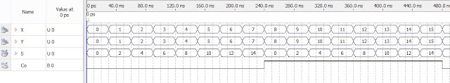
The simulation waveform demonstrates the accurate functional operations of the 4-bit ripple-carry adder that is implemented in Verilog above.
Recommended Verilog projects:
2. Verilog code for FIFO memory
3. Verilog code for 16-bit single-cycle MIPS processor
4. Programmable Digital Delay Timer in Verilog HDL
5. Verilog code for basic logic components in digital circuits
6. Verilog code for 32-bit Unsigned Divider
7. Verilog code for Fixed-Point Matrix Multiplication
8. Plate License Recognition in Verilog HDL
9. Verilog code for Carry-Look-Ahead Multiplier
10. Verilog code for a Microcontroller
11. Verilog code for 4x4 Multiplier
12. Verilog code for Car Parking System
13. Image processing on FPGA using Verilog HDL
14. How to load a text file into FPGA using Verilog HDL
15. Verilog code for Traffic Light Controller
16. Verilog code for Alarm Clock on FPGA
17. Verilog code for comparator design
18. Verilog code for D Flip Flop
19. Verilog code for Full Adder
20. Verilog code for counter with testbench
21. Verilog code for 16-bit RISC Processor
22. Verilog code for button debouncing on FPGA
23. Verilog Testbench for bidirectional/ inout ports
24. Tic Tac Toe Game in Verilog and LogiSim
25. 32-bit 5-stage Pipelined MIPS Processor in Verilog (Part-1)
26. 32-bit 5-stage Pipelined MIPS Processor in Verilog (Part-2)
27. 32-bit 5-stage Pipelined MIPS Processor in Verilog (Part-3)
30. N-bit Adder Design in Verilog25. 32-bit 5-stage Pipelined MIPS Processor in Verilog (Part-1)
26. 32-bit 5-stage Pipelined MIPS Processor in Verilog (Part-2)
27. 32-bit 5-stage Pipelined MIPS Processor in Verilog (Part-3)
31. Verilog vs VHDL: Explain by Examples
32. Verilog code for Clock divider on FPGA
33. How to generate a clock enable signal in Verilog
34. Verilog code for PWM Generator
35. Verilog coding vs Software Programming
36. Verilog code for Moore FSM Sequence Detector
37. Verilog code for 7-segment display controller on Basys 3 FPGA
38. Verilog code for interfacing FPGA with a mouse


No comments:
Post a Comment