

This Verilog project is to present a full Verilog code for Sequence Detector using Moore FSM. A Verilog Testbench for the Moore FSM sequence detector is also provided for simulation.
The Moore FSM keeps detecting a binary sequence from a digital input and the output of the FSM goes high only when a "1011" sequence is detected. The state diagram of the Moore FSM for the sequence detector is shown in the following figure.

It is noted that the Moore FSM output depends on only the current state of the FSM. The state diagram of the Moor FSM for the sequence detector is as follows:

Verilog code for the Moore FSM Sequence Detector is designed based on the state diagram and block diagram of the Moore FSM:
// fpga4student.com: FPGA projects, Verilog projects, VHDL projects
// Verilog project: Verilog code for Sequence Detector using Moore FSM
// The sequence being detected is "1011" or One Zero One One
module Sequence_Detector_MOORE_Verilog(sequence_in,clock,reset,detector_out
    );
input clock; // clock signal
input reset; // reset input
input sequence_in; // binary input
output reg detector_out; // output of the sequence detector
parameter  Zero=3'b000, // "Zero" State
  One=3'b001, // "One" State
  OneZero=3'b011, // "OneZero" State
  OneZeroOne=3'b010, // "OnceZeroOne" State
  OneZeroOneOne=3'b110;// "OneZeroOneOne" State
reg [2:0] current_state, next_state; // current state and next state
// sequential memory of the Moore FSM
always @(posedge clock, posedge reset)
begin
 if(reset==1)
 current_state <= Zero;// when reset=1, reset the state of the FSM to "Zero" State
 else
 current_state <= next_state; // otherwise, next state
end
// combinational logic of the Moore FSM
// to determine next state
always @(current_state,sequence_in)
begin
 case(current_state)
 Zero:begin
  if(sequence_in==1)
   next_state = One;
  else
   next_state = Zero;
 end
 One:begin
  if(sequence_in==0)
   next_state = OneZero;
  else
   next_state = One;
 end
 OneZero:begin
  if(sequence_in==0)
   next_state = Zero;
  else
   next_state = OneZeroOne;
 end
 OneZeroOne:begin
  if(sequence_in==0)
   next_state = OneZero;
  else
   next_state = OneZeroOneOne;
 end
 OneZeroOneOne:begin
  if(sequence_in==0)
   next_state = OneZero;
  else
   next_state = One;
 end
 default:next_state = Zero;
 endcase
end
// combinational logic to determine the output
// of the Moore FSM, output only depends on current state
always @(current_state)
begin
 case(current_state)
 Zero:   detector_out = 0;
 One:   detector_out = 0;
 OneZero:  detector_out = 0;
 OneZeroOne:  detector_out = 0;
 OneZeroOneOne:  detector_out = 1;
 default:  detector_out = 0;
 endcase
end
endmodule
Verilog Testbench for the Moore FSM Sequence Detector:
`timescale 1ns / 1ps
// fpga4student.com: FPGA projects, Verilog projects, VHDL projects
// Verilog project: Verilog code for Sequence Detector using Moore FSM
// Verilog Testbench for Sequence Detector using Moore FSM
module tb_Sequence_Detector_Moore_FSM_Verilog;

 // Inputs
 reg sequence_in;
 reg clock;
 reg reset;

 // Outputs
 wire detector_out;

 // Instantiate the Sequence Detector using Moore FSM
 Sequence_Detector_MOORE_Verilog uut (
  .sequence_in(sequence_in),
  .clock(clock),
  .reset(reset),
  .detector_out(detector_out)
 );
 initial begin
 clock = 0;
 forever #5 clock = ~clock;
 end
 initial begin
  // Initialize Inputs
  sequence_in = 0;
  reset = 1;
  // Wait 100 ns for global reset to finish
  #30;
      reset = 0;
  #40;
  sequence_in = 1;
  #10;
  sequence_in = 0;
  #10;
  sequence_in = 1;
  #20;
  sequence_in = 0;
  #20;
  sequence_in = 1;
  #20;
  sequence_in = 0;
  // Add stimulus here

 end

endmodule
Simulation Waveform of the sequence detector using Moore FSM in Verilog:
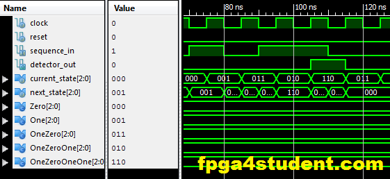
The simulation waveform of the sequence detector shows exactly how a Moore FSM works. Next state of the Moore FSM depends on the sequence input and the current state. The output of the Moore FSM only depends on the current state. The output of the sequence detector only goes high when the "1011" sequence is detected.
31. Verilog vs VHDL: Explain by Examples
32. Verilog code for Clock divider on FPGA
33. How to generate a clock enable signal in Verilog
34. Verilog code for PWM Generator
35. Verilog coding vs Software Programming
36. Verilog code for Moore FSM Sequence Detector
37. Verilog code for 7-segment display controller on Basys 3 FPGA
Recommended Verilog projects:
2. Verilog code for FIFO memory
3. Verilog code for 16-bit single-cycle MIPS processor
4. Programmable Digital Delay Timer in Verilog HDL
5. Verilog code for basic logic components in digital circuits
6. Verilog code for 32-bit Unsigned Divider
7. Verilog code for Fixed-Point Matrix Multiplication
8. Plate License Recognition in Verilog HDL
9. Verilog code for Carry-Look-Ahead Multiplier
10. Verilog code for a Microcontroller
11. Verilog code for 4x4 Multiplier
12. Verilog code for Car Parking System
13. Image processing on FPGA using Verilog HDL
14. How to load a text file into FPGA using Verilog HDL
15. Verilog code for Traffic Light Controller
16. Verilog code for Alarm Clock on FPGA
17. Verilog code for comparator design
18. Verilog code for D Flip Flop
19. Verilog code for Full Adder
20. Verilog code for counter with testbench
21. Verilog code for 16-bit RISC Processor
22. Verilog code for button debouncing on FPGA
23. Verilog Testbench for bidirectional/ inout ports
24. Tic Tac Toe Game in Verilog and LogiSim
25. 32-bit 5-stage Pipelined MIPS Processor in Verilog (Part-1)
26. 32-bit 5-stage Pipelined MIPS Processor in Verilog (Part-2)
27. 32-bit 5-stage Pipelined MIPS Processor in Verilog (Part-3)
30. N-bit Adder Design in Verilog25. 32-bit 5-stage Pipelined MIPS Processor in Verilog (Part-1)
26. 32-bit 5-stage Pipelined MIPS Processor in Verilog (Part-2)
27. 32-bit 5-stage Pipelined MIPS Processor in Verilog (Part-3)
31. Verilog vs VHDL: Explain by Examples
32. Verilog code for Clock divider on FPGA
33. How to generate a clock enable signal in Verilog
34. Verilog code for PWM Generator
35. Verilog coding vs Software Programming
36. Verilog code for Moore FSM Sequence Detector
37. Verilog code for 7-segment display controller on Basys 3 FPGA


can you please explain why the assingment statement for the state register (current state <= next state, current state <= zero) is <= and not simply =.
ReplyDeleteFor sequential logic (registers), it is recommended to use non-blocking assignment. For combinational logic, blocking assignment is recommended. You can read more about them.
Delete