

Last time, I presented in detail what actually FPGA programming is and how to get started with FPGA design. A brief history of Verilog and VHDL was also discussed. If you search for the difference between Verilog and VHDL, you will see many difference pages discussing this HDL language war, but most of them are short and not well-explained by examples for facilitating beginners or students' understanding.
The difference between Verilog and VHDL will be explained in detail by examples in this post. The advantages and disadvantages of Verilog and VHDL will be also discussed.

HDL Modeling Capacity: Verilog vs VHDL
First of all, let's discuss hardware modeling capacities of Verilog and VHDL since they are both hardware description languages for modeling hardware.
The following graph shows the HDL modeling capacity of Verilog and VHDL in terms of behavioral levels of hardware abstraction.
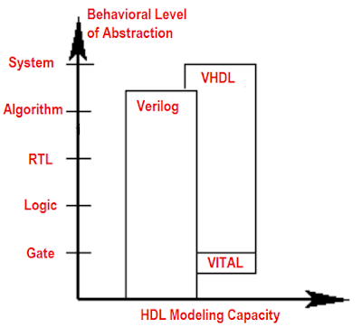
Graph source: Douglas J. Smith, "VHDL & Verilog Compared & Contrasted Plus Modeled Example Written in VHDL, Verilog, and C"
Low-Level Modeling
As shown in the graph above, Verilog and VHDL are both capable of modeling hardware. However, in terms of low-level hardware modeling, Verilog is better than VHDL. It is reasonable because Verilog is originally created for modeling and simulating logic gates. In fact, Verilog has built-in primitives or low-level logic gates so that designers can instantiate the primitives in Verilog code while VHDL does not have it.
Verilog's gate primitives: and, nand, or, nor, xor, xnor, buf, not, bufif0, notif0, bufif1, notif1, pullup, pulldown.
Verilog's switch primitives: pmos, nmos, rpmos, rnmos, cmos, rcmos, tran, rtran, tranif0, rtranif0, tranif1, rtranif1.
Verilog's switch primitives: pmos, nmos, rpmos, rnmos, cmos, rcmos, tran, rtran, tranif0, rtranif0, tranif1, rtranif1.
More importantly, Verilog supports User-Defined Primitives (UDP) so that designers can define their own cell primitives. This feature is especially necessary and popular for ASICs designers.
Below are Verilog examples on how to instantiate gate primitives in Verilog code:
or #5 u1(x,y,z);
and #10 u2(i1,i2,i3);
ADC_CIRCUIT u3(in1,out1,out2,clock);
// ADC_CIRCUIT is an User-Defined Primitive for
// Analog to Digital Converter for example.
The VHDL equivalent of some low-level built-in gate primitives in Verilog can be achieved by using logic operators such as NOT, AND, NAND, OR, NOR, XOR, XNOR.
Below are examples of VHDL equivalent code for Verilog gate primitives:
or u1(x,y,z); in Verilog <=> x <= y OR z; in VHDL
and u2(i1,i2,i3); (Verilog) <=> i3 <= i2 AND i3; in VHDL
To support UDP feature like in Verilog, VITAL (VHDL Initiative Towards ASIC Libraries) came out to enable ASIC designers creating their own cell primitives or ASIC libraries in VITAL-compliant VHDL as shown in the graph above. Even though, VHDL still may not achieve what Verilog can support for low-level hardware modeling. Thus, if I were an ASIC designer, I would prefer Verilog over VHDL.
High-level Modeling
On the other hand, VHDL is better than Verilog in terms of high-level hardware modeling as illustrated in the mentioned graph. VHDL provides more features and constructs for high-level hardware modeling compared to Verilog. Following are major different features for supporting high-level hardware modeling when comparing VHDL with Verilog:
- User-Defined Data types in VHDL
Verilog has very simple data types and it's all defined by Verilog language (users cannot define their own data types in Verilog). Verilog has two main data types including net data types (for connecting components together such as wire (most popular), wor, wand, tri, trior, etc.) and variable data types (for temporary storage such as reg (most popular), integer, time, real, and realtime). VHDL supports many different data types including predefined VHDL data types and User-Defined data types. Predefined VHDL data types include bit, bit_vector, string, time, boolean, character, and numeric (real or integer). VHDL allows designers to define different types based on the predefined VHDL data types; this is a good feature for complex and high-level systems which may use many different data types. Below is an example VHDL code for defining new data types:
type int_8bit is range 0 to 255 -- define 8-bit unsigned numbers
signal i : int_8bit;
type state_FSM is (Idle, start, calculate , finish, delay)
-- define symbolic states to represent FSM states.
signal current_state, next_state: state_FSM;
- Package for Design Reuse in VHDL
Packages in VHDL are commonly used for data types and subprograms' declaration. The subprograms or data types declared in VHDL package can be used in many different entities or architectures. For example:
package fsm_type is
type FSM_states is (IDLE, TRANSMIT, RECEIVE, STOP);
end package
-- to use the FSM_states type in an entity or architecture
-- use the following statement on top of the entity
use work.fsm_type.all
entity example is
There is no package definition in Verilog. The closest Verilog equivalent to VHDL package is `include Verilog compiler directive. Functions or definitions can be separately saved in another file and then use it in a module by using `include directive. Below is a Verilog example code:
// Below is the content of "VerilogVsVHDL.h" file
`define INPUT_VERILOG "./test_VerilogvsVHDL.hex" // Input file name
`define OUTPUT_VHDL "VHDL.bmp" // Output file name
`define VERILOG_VHDL_DIFFERENCE

// Then call it in every single module that you want to use the definition above
`include "VerilogVsVHDL.h"
- Configuration Statement in VHDL
A VHDL design can obtain many design entities with different architectures for one entity. Configuration statements associate the exact design entity to a component instance in a design. When there is more than one architecture in an entity, configuration statements continue to specify the desired design architecture is assigned to the entity for synthesis or simulation. This feature is very helpful when VHDL designers need to manage a large high-level design.
Following is a VHDL example code for configuration statement:
entity BUF is
  generic (DELAY : TIME := 10 ns);
  port ( BUF_IN : in BIT; BUF_OUT : out BIT);
end BUF;
-- The first design architecture for BUF
architecture STRUCT_BUF1 of BUF is
signal temp: bit;
begin
  BUF_OUT <= not temp after DELAY;
  temp <= not BUF_IN after DELAY;
end STRUCT_BUF1;
-- The second design architecture for BUF
architecture STRUCT_BUF2 of BUF is
begin
  BUF_OUT <= BUF_IN after 2*DELAY;;
end STRUCT_BUF2;
-- Testbench to simulate BUF entity
entity BUF_TESTBENCH is
end BUF_TESTBENCH;
architecture STRUCT_BUF_TEST of BUF_TESTBENCH is
signal TEST1, TEST2 : BIT := '1';
-- BUF_COMP component declaration:
component BUF_COMP is
  generic (TIME_DELAY : TIME);
  port ( IN1 : in BIT; OUT1 : out BIT );
end component;
begin
  -- instantiation of BUF_COMP component:
  DUT:BUF_COMP generic map (10 ns) port map (TEST1,TEST2);
end STRUCT_BUF_TEST;
-- Configuration specify the design entity and architecture
-- for the DUT component instance in the testbench above
configuration CONFIG_BUF of TEST_BUF is
-- Associate BUF_COMP component instance to BUF design entity
-- and STRUCT_BUF1 design architecture for simulation
for STRUCT_BUF_TEST
  for DUT : BUF_COMP
    use entity WORK.BUF (STRUCT_BUF1)
    generic map (DELAY => TIME_DELAY)
    port map (BUF_IN => IN1, BUF_OUT => OUT1);
  end for;
end for ;
end CONFIG_BUF;
Configuration blocks are also added to Verilog-2001.
- Library Management in VHDL
When looking at Verilog and VHDL code at the same time, the most obvious difference is Verilog does not have library management while VHDL does include design libraries on the top of the code. VHDL libraries contain compiled architectures, entities, packages, and configurations. This feature is very useful when managing large design structures. Examples of packages and configurations in VHDL are already given above. Following is VHDL example code for library management in VHDL:
-- library management in VHDL
library IEEE;
use IEEE.STD_LOGIC_1164.ALL;
use IEEE.numeric_std.all;
use work.clock_div.all;
In short, VHDL is better at high-level hardware modeling than Verilog. Since FPGA design flow does not require low-level hardware modeling, I would prefer VHDL over Verilog if I were an FPGA designer.
It is worth mentioning that SystemVerilog was created to enhance the weakness of Verilog language in high-level modeling by adding high-level features and constructs like in VHDL to Verilog for verification. SystemVerilog now is widely used for IC Verification.
Verboseness: Verilog vs VHDL
- VHDL is strongly typed vs Verilog is loosely typed
VHDL is a very strongly typed hardware description language so VHDL code must be correctly written with matched and defined data types. It means that there will be a compiler error if you mix data types or mismatch signals when assigning in VHDL. On the other hand, Verilog is a loosely typed language. In Verilog, you can mix data types or mismatch signals when assigning. Below is a VHDL example code for mismatching signals:
signal test_reg1:  std_logic_vector(3 downto 0);
signal test_reg2:  std_logic_vector(7 downto 0);
test_reg2 <= test_reg1;
-- You cannot assign a 4-bit signal to an 8-bit signal
-- in VHDL, it will introduce a syntax error below:
-- Width mismatch. Expected width 8, Actual width is 4
-- for dimension 1 of test_reg1.
When compiling the VHDL code above, there will be a syntax error "Width mismatch. Expected width 8, Actual width is 4". If the VHDL code is changed to "test_reg2 <= "0000"&test_reg1;" for matching the bit width, there will be no syntax errors.
What if you assign a 4-bit signal to an 8-bit signal in Verilog?
What if you assign a 4-bit signal to an 8-bit signal in Verilog?
  wire [3:0] test1;
  wire [7:0] test2;
  // In Verilog, you can assign 4-bit signal to 8-bit signal.
  assign test2 = test1;
  // there will be no syntax error during synthesis
Below is another VHDL example for mixing data types when assigning signals:
signal test1: std_logic_vector(7 downto 0);
signal test2: integer;
test2 <= test1;
-- Syntax Error: type of test2 is incompatile with type of test1
library IEEE;
USE ieee.numeric_std.ALL;
signal test1: std_logic_vector(3 downto 0);
signal test2: integer;
-- Use IEEE.NUMBERIC_STD.ALL Library for this conversion
test2 <= to_integer(unsigned(test1));
-- No syntax errors this time
  reg [3:0] test1;
  integer test2;
  always @(test1) begin
   test2 = test1;
  end
         // NO syntax errors when compiling
- VHDL Complex data types vs Verilog simple data types
As mentioned above, VHDL has many different complex data types and users can also define many other complex data types. This also makes VHDL more verbose than Verilog since Verilog only has 2 major data types and user-defined data types are not allowed in Verilog.
In other words, to model the same circuit, VHDL code normally is more verbose and longer than Verilog code because we need to perform conversions between different complex data types in VHDL due to its strong typing. It can be an advantage or disadvantage. Indeed, it is more likely that VHDL compiler would introduce syntax errors when you assign something wrong in your VHDL code. When you successfully compile a VHDL code, it is more likely that your VHDL code is working compared to Verilog. Verilog, on the other hand, is loosely typed, more concise, and simpler; but after successfully compiling, it is more likely that there are still errors in your Verilog code.
Below is another example code that makes VHDL more verbose than Verilog:
-- VHDL code for ALU
process(SEL,ABUS,BBUS,tmp1,tmp2)
begin
case(SEL) is
 when "0000" =>  ALUOUT <= tmp1; -- ADD
 when "0001" =>  ALUOUT <= tmp2;-- SUB
 when "0010" =>  ALUOUT <= BBUS; -- AND
 when others => ALUOUT <= ABUS;
 end case;
end process;
// Verilog equivalent to VHDL ALU
assign ALUOUT=(SEL==0)?tmp1:((SEL==1)?tmp2:((SEL==2)?BBUS:ABUS));
The case, if else, when/else, with/select statement in VHDL can be expressed less verbose in Verilog using conditional operator (?) as shown in the above example.
For example, to instantiate the entity clk_div in VHDL, a component declaration will be added in the architecture code like this:
Other differences between Verilog and VHDL:
- Verilog is like C programming language, while VHDL is like Ada or Pascal programming language
- Verilog is case-sensitive while VHDL is not. It means that DAta1 and Data1 are two different signals in Verilog, but both are the same signals in VHDL.
- In Verilog, to use a component instance in a module, you just need to instantiate it in the module with a correct port map. In VHDL, before instantiating the instance, the component generally needs to be declared the architecture or in a package if you use the old instantiation statement as the following example. In VHDL-93, you can instantiate the entity directly like this: "Label_name: entity work.component_name port map (port list);".
For example, to instantiate the entity clk_div in VHDL, a component declaration will be added in the architecture code like this:architecture Behavioral of digital_clock is -- component declaration before instantiation below component clk_div port ( clk_50: in std_logic; clk_1s : out std_logic ); end component; signal clk, clk_1s: std_logic; begin
-- component instantiation
create_1s_clock: clk_div port map (clk_50 => clk, clk_1s => clk_1s);
end
Or declare the component in a package for reuse:
library IEEE;
use IEEE.STD_LOGIC_1164.ALL;
package clock_div_pack is
component clk_div is
 port (
         clk_50: in std_logic;
         clk_1s : out std_logic
 );
end component clk_div;
end package;
-- Declare the component in a separate package and
-- reuse by using the following statement:
use work.clock_div_pack.all;
entity clock is
end clock;
architecture Behavioral of clock is
signal clk, clk_1s: std_logic;
begin
create_1s_clock: clk_div port map (clk_50 => clk, clk_1s => clk_1s);
end
Example code for directly instantiating the entity in VHDL-93:
create_1s_clock: entity work.clk_div port map (clk_50 => clk, clk_1s => clk_1s);
- Verilog has compiler directives such as `timescale (declare time units and precision for delays), `define (declare text string as a macro name), `ifdef, ifndef `else `elseif `endif (conditional compiling), `include (include a file which can contain functions or other declarations), etc. VHDL does not have compiler directives.
- VHDL supports enumerated and record data type which allows users to define multiple signals for one data type. Verilog does not support enumerated and record type. Below is a VHDL code for enumerated and record type:
type FSM is (IDLE, TEST, VERILOGvsVHDL, STOP, FPGA4student);
-- enumerated type
type int_4 is range 0 to 15;
-- record tye in VHDL
type record_example is record
 data1: integer;
 data2: int_4;
 data3: FSM;
end record;
- Etc.
You may like this:
Verilog projects on FPGA4student
VHDL projects on FPGA4student
FPGA projects on FPGA4student
What is an FPGA? How does it work?
What is FPGA Programming? FPGA vs Software programming
Recommended and affordable Xilinx FPGA boards for students
Recommended and affordable Altera FPGA boards for students
Image Processing on FPGA using Verilog
A microcontroller design in Verilog


No comments:
Post a Comment