

In this VHDL project, a simple low pass FIR filter is implemented in VHDL for ECG Denoising. VHDL code for the FIR filter is fully presented.
The VHDL code for the FIR filter is simulated and verified by comparing the simulated results in Modelsim with the correct results generated from Matlab. Sample ECG inputs are provided in input.txt files, the VHDL filter code reads those ECG files, apply digital filtering, and write the results into output.txt files for verification.
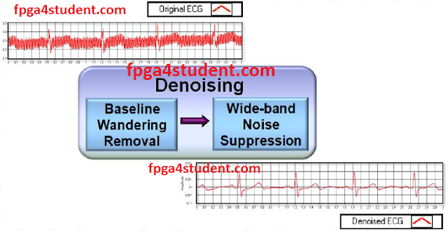
It is obvious that one of the most critical steps in ECG digital signal processing is noise filtering because ECG signals are noisily affected by many different sources such as Baseline Wander, EMG interference, and power line noise. Those noises can be reduced by many filters as shown in the figure above. This project is to implement a low pass FIR Filter in VHDL to reduce high-frequency noise and power-line interference.
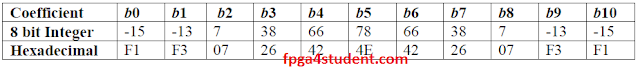
The specification of the filter as follows:
- Order: 10
- Tap: 11
- 8-bit signed integer coefficients as shown below:
In this project, the regular implementation of the FIR filter as shown in the following figure is implemented in VHDL.
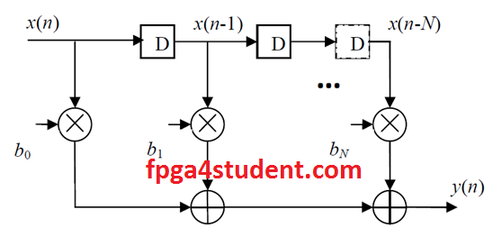
The FIR filter is basically implemented by using D-Flip-Flops, signed multipliers and adders. A basic block includes one N-bit register, one multiplier, and one adder. The VHDL generate statement is used to generate the full design using the basic block.
VHDL code for the low pass FIR filter:
Library IEEE;
 USE IEEE.Std_logic_1164.all;
 USE IEEE.Std_logic_signed.all;
 -- fpga4student.com: FPGA projects, VHDL projects, Verilog projects
 -- LOW pass FIR filter for ECG Denoising
 -- VHDL project: VHDL code for FIR filter
 entity FIR_RI is  -- VHDL projects
 generic (
           input_width          : integer     :=8               ;-- set input width by user
           output_width     : integer     :=16               ;-- set output width by user
           coef_width          : integer     :=8               ;-- set coefficient width by user
           tap                    : integer     :=11               ;-- set filter order
           guard               : integer     :=0)               ;-- log2(tap)+1
 port(
      Din          : in      std_logic_vector(input_width-1 downto 0)     ;-- input data
      Clk          : in      std_logic                                             ;-- input clk
      reset     : in      std_logic                                             ;-- input reset
      Dout     : out      std_logic_vector(output_width-1 downto 0))     ;-- output data
 end FIR_RI;
 architecture behaivioral of FIR_RI is
 -- N bit Register
 component N_bit_Reg
 generic (
           input_width          : integer     :=8
           );
   port(
    Q : out std_logic_vector(input_width-1 downto 0);
    Clk :in std_logic;
    reset :in std_logic;
    D :in std_logic_vector(input_width-1 downto 0)
   );
 end component;
 -- fpga4student.com: FPGA projects, VHDL projects, Verilog projects
 type Coeficient_type is array (1 to tap) of std_logic_vector(coef_width-1 downto 0);
 -----------------------------------FIR filter coefficients----------------------------------------------------------------
 constant coeficient: coeficient_type :=
                               (     X"F1",
                                    X"F3",
                                    X"07",
                                    X"26",
                                    X"42",
                                    X"4E",
                                    X"42",
                                    X"26",
                                    X"07",
                                    X"F3",
                                    X"F1"
                                    );
 ----------------------------------------------------------------------------------------------
 type shift_reg_type is array (0 to tap-1) of std_logic_vector(input_width-1 downto 0);
 signal shift_reg : shift_reg_type;
 type mult_type is array (0 to tap-1) of std_logic_vector(input_width+coef_width-1 downto 0);
 signal mult : mult_type;
 type ADD_type is array (0 to tap-1) of std_logic_vector(input_width+coef_width-1 downto 0);
 signal ADD: ADD_type;
 begin
 -- fpga4student.com: FPGA projects, VHDL projects, Verilog projects
        shift_reg(0)     <= Din;
           mult(0)<= Din*coeficient(1);
           ADD(0)<= Din*coeficient(1);
           GEN_FIR:
           for i in 0 to tap-2 generate
           begin
                 -- N-bit reg unit
                 N_bit_Reg_unit : N_bit_Reg generic map (input_width => 8)
                 port map ( Clk => Clk,
                                    reset => reset,
                                    D => shift_reg(i),
                                    Q => shift_reg(i+1)
                                    );
                -- filter multiplication
                mult(i+1)<= shift_reg(i+1)*coeficient(i+2);
                -- filter conbinational addition
                ADD(i+1)<=ADD(i)+mult(i+1);
           end generate GEN_FIR;
           Dout <= ADD(tap-1);
 end Architecture;

 Library IEEE;
 USE IEEE.Std_logic_1164.all;

 -- fpga4student.com: FPGA projects, VHDL projects, Verilog projects
 -- LOW pass FIR filter for ECG Denoising
 -- VHDL project: VHDL code for FIR filter
 -- N-bit Register in VHDL
 entity N_bit_Reg is
 generic (
           input_width          : integer     :=8
           );
   port(
    Q : out std_logic_vector(input_width-1 downto 0);
    Clk :in std_logic;
    reset :in std_logic;
    D :in std_logic_vector(input_width-1 downto 0)
   );
 end N_bit_Reg;
  -- fpga4student.com: FPGA projects, VHDL projects, Verilog projects
 architecture Behavioral of N_bit_Reg is
 begin
      process(Clk,reset)
      begin
           if (reset = '1') then
                Q <= (others => '0');
        elsif ( rising_edge(Clk) ) then
                Q <= D;
       end if;
      end process;
 end Behavioral;
Testbench VHDL code for the FIR filter:
 Library IEEE;
 USE IEEE.Std_logic_1164.all;
 USE IEEE.numeric_std.all;
 Use STD.TEXTIO.all;
  -- fpga4student.com: FPGA projects, VHDL projects, Verilog projects
  -- VHDL project: VHDL code for FIR filter
  -- Testbench VHDL code for FIR Filter
 entity TB_FIR is
 end TB_FIR;
 architecture behaivioral of TB_FIR is
 Component FIR_RI is
 generic (
           input_width          : integer     :=8               ; -- set input width by user
           output_width     : integer     :=16               ; -- set output width by user
           coef_width          : integer     :=8               ; -- set coefficient width by user
           tap                    : integer     :=11               ; -- set filter order
           guard               : integer     :=4)                    ; -- log2(tap)+1
 port(
      Din          : in      std_logic_vector(input_width-1 downto 0)     ;     -- input data
      Clk          : in      std_logic                              ;               -- input clk
      reset     : in      std_logic                                   ;               -- input reset
      Dout     : out      std_logic_vector(output_width-1 downto 0))     ;-- output data
 end Component;
 signal Din          :      std_logic_vector(7 downto 0)     ;
 signal Clk          :      std_logic:='0'                              ;
 signal reset     :      std_logic:='1'                              ;
 signal output_ready     :      std_logic:='0';
 signal Dout          :      std_logic_vector(15 downto 0)     ;
 signal input: std_logic_vector(7 downto 0);
 file my_input : TEXT open READ_MODE is "input101.txt";
 file my_output : TEXT open WRITE_MODE is "output101_functional_sim.txt";
 begin
   -- fpga4student.com: FPGA projects, VHDL projects, Verilog projects
   FIR_int : FIR_RI
           generic map(
                          input_width          =>     8,
           output_width     =>     16,
           coef_width          =>     8,
           tap                 =>     11,
                          guard               =>     0)
           port map     (
                          Din                    => Din,
                          Clk                    => Clk,
                          reset               => reset,
                          Dout               => Dout
                );
           process(clk)
           begin
           Clk          <= not Clk after 10 ns;
           end process;
           reset     <= '1', '1' after 100 ns, '0' after 503 ns;
     -- fpga4student.com: FPGA projects, VHDL projects, Verilog projects
     -- Writing output result to output file
           process(clk)
           variable my_input_line : LINE;
           variable input1: integer;
           begin
                if reset ='1' then
                     Din <= (others=> '0');
                     input <= (others=> '0');
                     output_ready <= '0';
                elsif rising_edge(clk) then
                     readline(my_input, my_input_line);
                     read(my_input_line,input1);
                     Din <= std_logic_vector(to_signed(input1, 8));
                     --Din<=input(7 downto 0);
                     output_ready <= '1';
                end if;
           end process;
           process(clk)
           variable my_output_line : LINE;
           variable input1: integer;
           begin
                if falling_edge(clk) then
                     if output_ready ='1' then
                          write(my_output_line, to_integer(signed(Dout)));
                          writeline(my_output,my_output_line);
                     end if;
                end if;
           end process;

 end Architecture;
After running simulations in Modelsim, the filtered output is written into output.txt for verification. The verification is done by comparing the output file with the correct result generated from Matlab.
Download sample inputs and output from Matlab
Recommended VHDL projects:
1. What is an FPGA? How VHDL works on FPGA
2. VHDL code for FIFO memory
3. VHDL code for FIR Filter
4. VHDL code for 8-bit Microcontroller
5. VHDL code for Matrix Multiplication
6. VHDL code for Switch Tail Ring Counter
7. VHDL code for digital alarm clock on FPGA
8. VHDL code for 8-bit Comparator
9. How to load a text file into FPGA using VHDL
10. VHDL code for D Flip Flop
11. VHDL code for Full Adder
12. PWM Generator in VHDL with Variable Duty Cycle
13. VHDL code for ALU
14. VHDL code for counters with testbench
15. VHDL code for 16-bit ALU
16. Shifter Design in VHDL
17. Non-linear Lookup Table Implementation in VHDL
18. Cryptographic Coprocessor Design in VHDL
19. Verilog vs VHDL: Explain by Examples
20. VHDL Code for Clock Divider on FPGA
21. How to generate a clock enable signal instead of creating another clock domain
22. VHDL code for debouncing buttons on FPGA
23. VHDL code for Traffic light controller
24. VHDL code for a simple 2-bit comparator
25. VHDL code for a single-port RAM
22. VHDL code for debouncing buttons on FPGA
23. VHDL code for Traffic light controller
24. VHDL code for a simple 2-bit comparator
25. VHDL code for a single-port RAM
26. VHDL code for Car Parking System using FSM
27. VHDL coding vs Software Programming


Like to run this on my Arty board but is having a hard time to get the ADC configured.Any help for a ADC interface available?
ReplyDeleteFind an ADC chip or module such as MCP3001 or PMOD ADC Digilent
Deletewhat is sampling frequency?
ReplyDeleteThis is a regular implementation of FIR Filter. It is not designed by using frequency sampling method.
DeleteHey,
ReplyDeleteI've got a problem with this line in the code : write(my_output_line, to_integer(signed(Dout))); The compilator in ISE is saying : "Second argument of write must have a constant value". I dont' know how to fix this issue. Thanks for your help
You compiled or synthesized the testbench, that's why you got that error. You only run simulation with the testbench. Synthesize the top level only (FIR_RI).
DeleteThanks for your quick help. Yes indeed, I've compiled the test bench. So, the testbench just has to be written as a module, I thought it was the main module (top level) to compile ? Sorry, I'm a beginner !!
DeleteThank you for the code, i am having a problem with input output and coefficient width . what are they for kaiser window or how to calculate them??
ReplyDeleteThey are defined by users
DeleteHi Loi,
ReplyDeleteMình gặp lỗi này khi chạy simulation."File input101.txt could not be opened"
Mình đã download file input về nhưng chưa biết phải đặt vào thư mục nào để chương trình đọc được
Mình cần phải đặt vào đâu nhỉ?
Cảm ơn bạn!
Bo vao folder ban chay simulation nhe.
DeleteDoes anyone have a MATLAB program with this filter implemented that gives the same output? I tried creating FIR filter using coefficients from this project, but I am getting completely different output.
ReplyDeleteif you use this VHDL code, you will generate the same output as Matlab.
Deletewill it work on xilinx ise too?
ReplyDeleteIt was simulated in Xilinx ISE.
Deletehi van. thank you for code.
ReplyDeletei have a doubt that you have applied text input through text bench, then how to apply it for fpga.
In that case, you need to create a synthesizable model to pass the text file data to the FIR filter.
DeleteWill it work for Altera Quartus Prime? How do I get the input file?
ReplyDeletesure it works. The input files are given above.
DeleteCho em hỏi, em copy code vào file .vht, rồi start compilation thì không có lỗi gì. Nhưng khi vào folder chạy simulation (đã có file input trong đó) thì không thấy file output đuôi .txt đâu. Không biết đây là lỗi gì hay cách em chạy mô phỏng bị sai? Mong được giúp đỡ. Em dùng Quartus II 12.1.
ReplyDeleteYou have to run simulation until output_ready = '1' so that the output file is written.
DeleteSample input and output files are not there anymore in the link you have provided. I request you to kindly provide it again.
ReplyDeleteSorry I have updated the link.
DeleteI did run modelsim simulator keeping 'input101.txt' file in project folder. i got 'output101_functional_sim.txt' file which is not same as 'output101.txt' sample file provided by you in the link.
ReplyDeleteNumber of values in 'output101_functional_sim.txt' file is very less than the number of values in 'output101.txt' file. Please help regarding it.
Double check your simulation. The code was verified and all the outputs were approximately matched with the provided samples.
DeleteFirst of all thank you for your code,
ReplyDeleteSecondly, can you provide the sample input and output files ("input101.txt" and "output101_functional_sim.txt").
hi can i use this code on papillo logic start . what are the hardware requirements
ReplyDeletewhich filter window did u use to get the coefficients
ReplyDeletehi, I have a question about the coefficients of the filter, how do you get the integers? The problem I got is, I have get the coefficients of the build-in low pass filter(Butterworh), which is so small, how could I translate this small number into VHDL? thanks!
ReplyDelete