

This FPGA project is about to help you interface the Basys 3 FPGA with OV7670 CMOS Camera in VHDL. It allows you to quickly start working on your DSP projects with real-time image/ video processing without worrying about the camera interface.

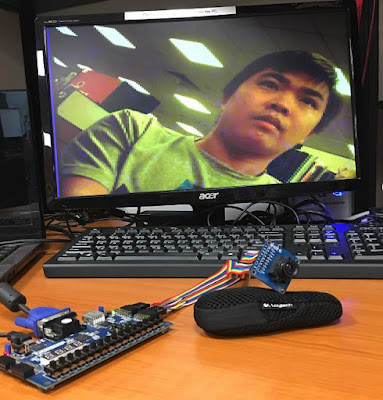
The camera chip being used is a cheap CMOS camera (~3-5USD), named OV7670. The camera has an image array of 656x488 pixels, of which 640x480 pixels are active. This work is based on the design by Mike Field - details of his design for Nexys 2, and Zedboard in Xilinx ISE. The camera connections to Basys 3 FPGA are shown in the picture above.
This project is to migrate the design in Xilinx ISE for Zedboard to Vivado Design Suite for Basys 3 FPGA with reconfigurable image sizes of 640x480, 320x240, and 160x120.
To interface with the OV7670 camera, followings are the most critical steps and modules:
1. Camera configuration (OV7670_controller.vhd): To configure the OV7670 camera properly, check its datasheet to know which communication protocol it supports for configuration and capturing data. In this case, it is an I2C-like SSCB interface so an I2C code is needed to communicate with the camera, configure it, and get image data. More details of the I2C-like interface can be found at i2c_sender.vhd. To configure it properly, check the device control register list. Beside the configuration for the output format (RGB, QVGA, QCIF, etc.), RGB format (RGB565, RGB555, etc.), timing signals (PCLK, HREF, VSYNC), the matrix coefficients including MTX1-MTX6 are important factors deciding the output image quality. More details of the control register values can be found at OV7670_registers.vhd.

I2C-like SCCB interface for communicating with the OV7670 camera
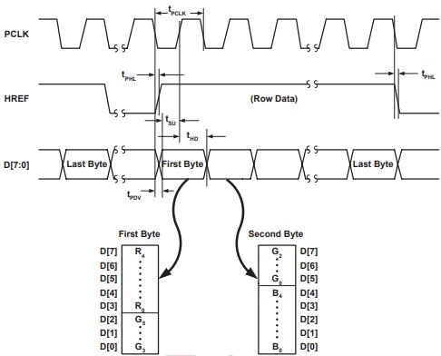
2. Capturing image data (OV7670_capture.vhd): After configuring the camera, the next step is to capture the image data. One more time, check the datasheet of the camera to see the output timing diagram of your selected output format. For example, in this project, the RGB565 format is chosen so the output timing diagram for RGB565 is used for properly capturing the RGB data from the output signals of the camera. Based on the timing diagram as follows, the OV7670_capture.vhd is designed.
3. Saving Image Data (frame_buffer.vhd): After being able to configure the camera and capture the image data properly, the image data is stored in an intermediate memory. The problem with Basys 3 FPGA is that the memory size of Basys 3 FPGA is not enough for 640x480 image size. To use the same settings for the camera and VGA controller with a full 640x480 image size without exceeding the BRAM of Basys 3 FPGA, the trick is to save only one pixel every 4 pixels for the 640x480 size. Then, we can reduce the frame buffer size by 4 times to fit Basys 3 FPGA while having a full image size of 640x480 on a VGA monitor. For the 320x240 and 160x120 sizes, it is designed to display in 320x240 image size by pressing the Left button, whereas pressing the Right button on Basys 3 FPGA is to choose to display in 160x120 frame size on the VGA monitor.
To do that, in Vivado, you can either upgrade the block memory file (frame_buffer.xco - generated by Core Generator in Xilinx ISE) to Vivado-suited LogiCore IP Block Memory v8.4 (frame_buffer.xci) while reducing the memory size by 4 times or use Block Memory Generator in the IP catalog of Vivado to create a new frame buffer with the depth of 131072 (17-bit address).

By doing so, you will get the newly updated frame buffer with 17-bit RAM address as follows:
-- FPGA4student.com: Basys 3 FPGA OV7670 Camera
-- Frame Buffer by Vivado IP LogiCore
LIBRARY ieee;
USE ieee.std_logic_1164.ALL;
USE ieee.numeric_std.ALL;

LIBRARY blk_mem_gen_v8_4_0;
USE blk_mem_gen_v8_4_0.blk_mem_gen_v8_4_0;

ENTITY frame_buffer IS
  PORT (
    clka : IN STD_LOGIC;
    wea : IN STD_LOGIC_VECTOR(0 DOWNTO 0);
    addra : IN STD_LOGIC_VECTOR(16 DOWNTO 0);
    dina : IN STD_LOGIC_VECTOR(11 DOWNTO 0);
    clkb : IN STD_LOGIC;
    addrb : IN STD_LOGIC_VECTOR(16 DOWNTO 0);
    doutb : OUT STD_LOGIC_VECTOR(11 DOWNTO 0)
  );
END frame_buffer;
4. Displaying the real-time video/image on a VGA monitor (vga.vhd): The final step is to display the image data saved in the frame buffer on a VGA monitor, and a VGA controller is required. Followings are the timing diagram and table for the VGA controller with the VGA clock of 25MHz.


 Full project file in Vivado for the OV7670 Camera on Basys 3 FPGA can be downloaded here.
Finally, the top-level VHDL code for the OV7670 camera on Basys 3 FPGA:
-- Based on the work for Zedboard FPGA by Mike Field <hamster@snap.net.nz>
-- OV7670 Camera with Basys 3 FPGA by FPGA4student.com
-- Module Name: top_level - Behavioral
-- Description: Top level module of the Zedboard OV7670 design
library IEEE;
use IEEE.STD_LOGIC_1164.ALL;
entity top_level is
    Port ( clk100          : in  STD_LOGIC;
           btnl            : in  STD_LOGIC;
           btnc            : in  STD_LOGIC;
           btnr            : in  STD_LOGIC;
           config_finished : out STD_LOGIC;

           vga_hsync : out  STD_LOGIC;
           vga_vsync : out  STD_LOGIC;
           vga_r     : out  STD_LOGIC_vector(3 downto 0);
           vga_g     : out  STD_LOGIC_vector(3 downto 0);
           vga_b     : out  STD_LOGIC_vector(3 downto 0);

           ov7670_pclk  : in  STD_LOGIC;
           ov7670_xclk  : out STD_LOGIC;
           ov7670_vsync : in  STD_LOGIC;
           ov7670_href  : in  STD_LOGIC;
           ov7670_data  : in  STD_LOGIC_vector(7 downto 0);
           ov7670_sioc  : out STD_LOGIC;
           ov7670_siod  : inout STD_LOGIC;
           ov7670_pwdn  : out STD_LOGIC;
           ov7670_reset : out STD_LOGIC
           );
end top_level;
architecture Behavioral of top_level is

 COMPONENT VGA
 PORT(
  CLK25 : IN std_logic;
                rez_160x120 : IN std_logic;
                rez_320x240 : IN std_logic;
  Hsync : OUT std_logic;
  Vsync : OUT std_logic;
  Nblank : OUT std_logic;
  clkout : OUT std_logic;
  activeArea : OUT std_logic;
  Nsync : OUT std_logic
  );
 END COMPONENT;

 COMPONENT ov7670_controller
 PORT(
  clk : IN std_logic;
  resend : IN std_logic;
  siod : INOUT std_logic;
  config_finished : OUT std_logic;
  sioc : OUT std_logic;
  reset : OUT std_logic;
  pwdn : OUT std_logic;
  xclk : OUT std_logic
  );
 END COMPONENT;

 COMPONENT debounce
 PORT(
  clk : IN std_logic;
  i : IN std_logic;
  o : OUT std_logic
  );
 END COMPONENT;

 COMPONENT frame_buffer
  PORT (
      clka : IN STD_LOGIC;
      wea : IN STD_LOGIC_VECTOR(0 DOWNTO 0);
      addra : IN STD_LOGIC_VECTOR(16 DOWNTO 0);
      dina : IN STD_LOGIC_VECTOR(11 DOWNTO 0);
      clkb : IN STD_LOGIC;
      addrb : IN STD_LOGIC_VECTOR(16 DOWNTO 0);
      doutb : OUT STD_LOGIC_VECTOR(11 DOWNTO 0)
    );
 END COMPONENT;
 COMPONENT ov7670_capture
 PORT(
                rez_160x120 : IN std_logic;
                rez_320x240 : IN std_logic;
  pclk : IN std_logic;
  vsync : IN std_logic;
  href : IN std_logic;
  d : IN std_logic_vector(7 downto 0);
  addr : OUT std_logic_vector(18 downto 0);
  dout : OUT std_logic_vector(11 downto 0);
  we : OUT std_logic
  );
 END COMPONENT;
 COMPONENT RGB
 PORT(
  Din : IN std_logic_vector(11 downto 0);
  Nblank : IN std_logic;
  R : OUT std_logic_vector(7 downto 0);
  G : OUT std_logic_vector(7 downto 0);
  B : OUT std_logic_vector(7 downto 0)
  );
 END COMPONENT;
 component clocking
 port (
                CLK_100           : in     std_logic;
                -- Clock out ports
                CLK_50          : out    std_logic;
                CLK_25          : out    std_logic);
 end component;
 COMPONENT Address_Generator
 PORT(
  CLK25       : IN  std_logic;
                rez_160x120 : IN std_logic;
                rez_320x240 : IN std_logic;
  enable      : IN  std_logic;
                vsync       : in  STD_LOGIC;
  address     : OUT std_logic_vector(18 downto 0)
  );
 END COMPONENT;
   signal clk_camera : std_logic;
   signal clk_vga    : std_logic;
   signal wren       : std_logic_vector(0 downto 0);
   signal resend     : std_logic;
   signal nBlank     : std_logic;
   signal vSync      : std_logic;
   signal nSync      : std_logic;

   signal wraddress  : std_logic_vector(18 downto 0);
   signal wrdata     : std_logic_vector(11 downto 0);

   signal rdaddress  : std_logic_vector(18 downto 0);
   signal rddata     : std_logic_vector(11 downto 0);
   signal red,green,blue : std_logic_vector(7 downto 0);
   signal activeArea : std_logic;

   signal rez_160x120 : std_logic;
   signal rez_320x240 : std_logic;
   signal size_select: std_logic_vector(1 downto 0);
   signal rd_addr,wr_addr  : std_logic_vector(16 downto 0);
begin
   vga_r <= red(7 downto 4);
   vga_g <= green(7 downto 4);
   vga_b <= blue(7 downto 4);

   rez_160x120 <= btnl;
   rez_320x240 <= btnr;
   your_instance_name : clocking
     port map
      (-- Clock in ports
       CLK_100 => CLK100,
       -- Clock out ports
       CLK_50 => CLK_camera,
       CLK_25 => CLK_vga);
       vga_vsync <= vsync;

 Inst_VGA: VGA PORT MAP(
  CLK25      => clk_vga,
                rez_160x120 => rez_160x120,
                rez_320x240 => rez_320x240,
  clkout     => open,
  Hsync      => vga_hsync,
  Vsync      => vsync,
  Nblank     => nBlank,
  Nsync      => nsync,
                activeArea => activeArea
 );
 Inst_debounce: debounce PORT MAP(
  clk => clk_vga,
  i   => btnc,
  o   => resend
 );
 Inst_ov7670_controller: ov7670_controller PORT MAP(
  clk             => clk_camera,
  resend          => resend,
  config_finished => config_finished,
  sioc            => ov7670_sioc,
  siod            => ov7670_siod,
  reset           => ov7670_reset,
  pwdn            => ov7670_pwdn,
  xclk            => ov7670_xclk
 );
 size_select <= btnl&btnr;

    with size_select select
    rd_addr <= rdaddress(18 downto 2) when "00",
        rdaddress(16 downto 0) when "01",
        rdaddress(16 downto 0) when "10",
        rdaddress(16 downto 0) when "11";

   with size_select select
    wr_addr <= wraddress(18 downto 2) when "00",
            wraddress(16 downto 0) when "01",
            wraddress(16 downto 0) when "10",
            wraddress(16 downto 0) when "11";
 Inst_frame_buffer: frame_buffer PORT MAP(
  addrb => rd_addr,
  clkb   => clk_vga,
  doutb        => rddata,

  clka   => ov7670_pclk,
  addra => wr_addr,
  dina      => wrdata,
  wea      => wren
 );
 Inst_ov7670_capture: ov7670_capture PORT MAP(
  pclk  => ov7670_pclk,
                rez_160x120 => rez_160x120,
                rez_320x240 => rez_320x240,
  vsync => ov7670_vsync,
  href  => ov7670_href,
  d     => ov7670_data,
  addr  => wraddress,
  dout  => wrdata,
  we    => wren(0)
 );
 Inst_RGB: RGB PORT MAP(
  Din => rddata,
  Nblank => activeArea,
  R => red,
  G => green,
  B => blue
 );
 Inst_Address_Generator: Address_Generator PORT MAP(
  CLK25 => clk_vga,
                rez_160x120 => rez_160x120,
                rez_320x240 => rez_320x240,
  enable => activeArea,
                vsync  => vsync,
  address => rdaddress
 );
end Behavioral;
The pin assignment XDC file for OV7670 Camera on Basys 3 FPGA:
## FPGA4student.com: Interfacing Basys 3 FPGA with OV7670 Camera
## Pin assignment
## Clock signal
set_property PACKAGE_PIN W5 [get_ports clk100]
 set_property IOSTANDARD LVCMOS33 [get_ports clk100]
 create_clock -add -name sys_clk_pin -period 10.00 -waveform {0 5} [get_ports clk100]

    ##VGA Connector
    set_property PACKAGE_PIN G19 [get_ports {vga_r[0]}]
        set_property IOSTANDARD LVCMOS33 [get_ports {vga_r[0]}]
    set_property PACKAGE_PIN H19 [get_ports {vga_r[1]}]
        set_property IOSTANDARD LVCMOS33 [get_ports {vga_r[1]}]
    set_property PACKAGE_PIN J19 [get_ports {vga_r[2]}]
        set_property IOSTANDARD LVCMOS33 [get_ports {vga_r[2]}]
    set_property PACKAGE_PIN N19 [get_ports {vga_r[3]}]
        set_property IOSTANDARD LVCMOS33 [get_ports {vga_r[3]}]
    set_property PACKAGE_PIN N18 [get_ports {vga_b[0]}]
        set_property IOSTANDARD LVCMOS33 [get_ports {vga_b[0]}]
    set_property PACKAGE_PIN L18 [get_ports {vga_b[1]}]
        set_property IOSTANDARD LVCMOS33 [get_ports {vga_b[1]}]
    set_property PACKAGE_PIN K18 [get_ports {vga_b[2]}]
        set_property IOSTANDARD LVCMOS33 [get_ports {vga_b[2]}]
    set_property PACKAGE_PIN J18 [get_ports {vga_b[3]}]
        set_property IOSTANDARD LVCMOS33 [get_ports {vga_b[3]}]
    set_property PACKAGE_PIN J17 [get_ports {vga_g[0]}]
        set_property IOSTANDARD LVCMOS33 [get_ports {vga_g[0]}]
    set_property PACKAGE_PIN H17 [get_ports {vga_g[1]}]
        set_property IOSTANDARD LVCMOS33 [get_ports {vga_g[1]}]
    set_property PACKAGE_PIN G17 [get_ports {vga_g[2]}]
        set_property IOSTANDARD LVCMOS33 [get_ports {vga_g[2]}]
    set_property PACKAGE_PIN D17 [get_ports {vga_g[3]}]
        set_property IOSTANDARD LVCMOS33 [get_ports {vga_g[3]}]
    set_property PACKAGE_PIN P19 [get_ports vga_hsync]
        set_property IOSTANDARD LVCMOS33 [get_ports vga_hsync]
    set_property PACKAGE_PIN R19 [get_ports vga_vsync]
        set_property IOSTANDARD LVCMOS33 [get_ports vga_vsync]
## LEDs
set_property PACKAGE_PIN U16 [get_ports {config_finished}]
 set_property IOSTANDARD LVCMOS33 [get_ports {config_finished}]
##Buttons
set_property PACKAGE_PIN U18 [get_ports btnc]
 set_property IOSTANDARD LVCMOS33 [get_ports btnc]
set_property PACKAGE_PIN W19 [get_ports btnl]
     set_property IOSTANDARD LVCMOS33 [get_ports btnl]
set_property PACKAGE_PIN T17 [get_ports btnr]
         set_property IOSTANDARD LVCMOS33 [get_ports btnr]
## OV7670 Camera header pins
##Pmod Header JB
##Sch name = JB1
set_property PACKAGE_PIN A14 [get_ports {ov7670_pwdn}]
 set_property IOSTANDARD LVCMOS33 [get_ports {ov7670_pwdn}]
##Sch name = JB2
set_property PACKAGE_PIN A16 [get_ports {ov7670_data[0]}]
 set_property IOSTANDARD LVCMOS33 [get_ports {ov7670_data[0]}]
##Sch name = JB3
set_property PACKAGE_PIN B15 [get_ports {ov7670_data[2]}]
 set_property IOSTANDARD LVCMOS33 [get_ports {ov7670_data[2]}]
##Sch name = JB4
set_property PACKAGE_PIN B16 [get_ports {ov7670_data[4]}]
 set_property IOSTANDARD LVCMOS33 [get_ports {ov7670_data[4]}]
##Sch name = JB7
set_property PACKAGE_PIN A15 [get_ports {ov7670_reset}]
 set_property IOSTANDARD LVCMOS33 [get_ports {ov7670_reset}]
##Sch name = JB8
set_property PACKAGE_PIN A17 [get_ports {ov7670_data[1]}]
 set_property IOSTANDARD LVCMOS33 [get_ports {ov7670_data[1]}]
##Sch name = JB9
set_property PACKAGE_PIN C15 [get_ports {ov7670_data[3]}]
 set_property IOSTANDARD LVCMOS33 [get_ports {ov7670_data[3]}]
##Sch name = JB10
set_property PACKAGE_PIN C16 [get_ports {ov7670_data[5]}]
 set_property IOSTANDARD LVCMOS33 [get_ports {ov7670_data[5]}]
##Pmod Header JC
##Sch name = JC1
set_property PACKAGE_PIN K17 [get_ports {ov7670_data[6]}]
 set_property IOSTANDARD LVCMOS33 [get_ports {ov7670_data[6]}]
##Sch name = JC2
set_property PACKAGE_PIN M18 [get_ports ov7670_xclk]
 set_property IOSTANDARD LVCMOS33 [get_ports ov7670_xclk]
##Sch name = JC3
set_property PACKAGE_PIN N17 [get_ports ov7670_href]
 set_property IOSTANDARD LVCMOS33 [get_ports ov7670_href]
##Sch name = JC4
set_property PACKAGE_PIN P18 [get_ports ov7670_siod]
 set_property IOSTANDARD LVCMOS33 [get_ports ov7670_siod]
 set_property PULLUP TRUE [get_ports ov7670_siod]
##Sch name = JC7
set_property PACKAGE_PIN L17 [get_ports {ov7670_data[7]}]
 set_property IOSTANDARD LVCMOS33 [get_ports {ov7670_data[7]}]
##Sch name = JC8
set_property PACKAGE_PIN M19 [get_ports ov7670_pclk]
 set_property IOSTANDARD LVCMOS33 [get_ports ov7670_pclk]
    set_property CLOCK_DEDICATED_ROUTE FALSE [get_nets {ov7670_pclk_IBUF}]
##Sch name = JC9
set_property PACKAGE_PIN P17 [get_ports ov7670_vsync]
 set_property IOSTANDARD LVCMOS33 [get_ports ov7670_vsync]
##Sch name = JC10
set_property PACKAGE_PIN R18 [get_ports ov7670_sioc]
 set_property IOSTANDARD LVCMOS33 [get_ports ov7670_sioc]
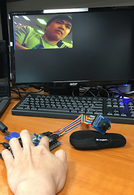
The image captured from the OV7670 Camera with Basys 3 FPGA displaying on the VGA monitor:
640x480:
320x240:
160x120:
Video Demo for OV7670 Camera on Basys 3 FPGA:
Recommended FPGA projects:


Where are the components?
ReplyDeleteYou only shared the top level code?