

Last time, I presented an FPGA tutorial on how to control the 4-digit 7-segment display on the Basys 3 FPGA board. Full Verilog and VHDL code for displaying a 4-digit number on the 7-segment display of FPGA Basys 3 were also provided.
This FPGA tutorial tells you how to interface a mouse with Xilinx Basys 3 FPGA board. The FPGA tutorial also provides a Verilog code for interfacing a mouse with FPGA Basys 3.

The on-board Auxiliary Function Microcontroller PIC24FJ128 allows Basys 3 FPGA to have USB HID host capability. Once the FPGA is programmed, the microcontroller is in USB HID host mode which can interface the FPGA with a mouse or keyboard connected to the USB type-A connector (J2) as shown in the following picture.
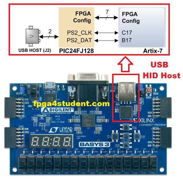
As illustrated in the picture above, the microcontroller's PS2_CLK and PS2_DAT signals are used to implement a PS/2 interface for communication with a mouse or keyboard. The other signals are to program the FPGA from a USB pen drive connected to the USB-HID port (J2) when the JP1 programming mode jumper is set to "USB".
In this FPGA tutorial, we only focus on the PS/2 interface of the onboard microcontroller for communication with a mouse. In this case, the microcontroller behaves like a PS/2 bus and a mouse that connected to the USB-HID port can use the two-wire (clock and data) serial bus (PS/2 protocol) to communicate with the FPGA as the host. The mouse sends clock and data signals to the FPGA when it is moved as shown in the following figure; otherwise, these signals are held high.

Download the whole Vivado project file: here.
Recommended FPGA projects for students:
In this FPGA tutorial, we only focus on the PS/2 interface of the onboard microcontroller for communication with a mouse. In this case, the microcontroller behaves like a PS/2 bus and a mouse that connected to the USB-HID port can use the two-wire (clock and data) serial bus (PS/2 protocol) to communicate with the FPGA as the host. The mouse sends clock and data signals to the FPGA when it is moved as shown in the following figure; otherwise, these signals are held high.
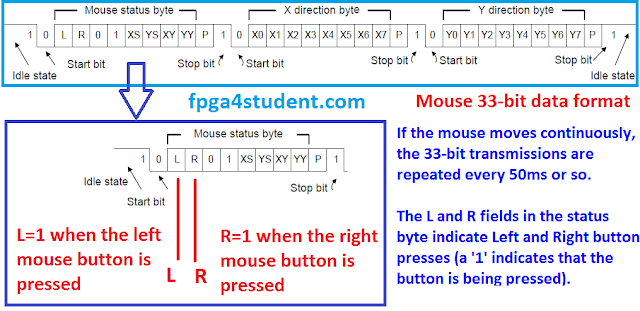
The 11-bit word data includes a ‘0’ start bit, 8 bits of data (LSB first), an odd parity bit, and followed by a ‘1’ stop bit. Three 11-bit words are transferred from the mouse to the FPGA, as shown in the following figure.
The three-byte movement data of the mouse include a mouse status byte, X-direction byte, and Y-direction byte. The data are valid only at the falling edge of the clock signal. The X-direction and Y-direction bytes are used to display the relative coordinate of the mouse which moving to the right/left generates positive/negative X and moving to the top/bottom generates positive/negative Y. The XS and YS bits in the mouse status byte are used as the 'sign' bits of the X and Y. The higher the X and Y the faster the speed of the mouse; the XY and YY bits indicate the movement overflow. The L and R bits in the mouse status byte are used to indicate if the Left and Right button of the mouse is pressed.
In short, the mouse always sends 33-bit data signals as formatted in the figure above to Basys 3 FPGA whenever the mouse is moved. The Left button click status is shown in the second bit of the data while the third bit indicates the Right button click status of the mouse. The X and Y coordinates are sent from the 13th-to-20th and 24th-to-30th bits of the 33-bit data, respectively.
In this FPGA tutorial, a Verilog code for interfacing a mouse with FPGA Basys 3 is presented. Every time the left button of the mouse is clicked, a 4-digit number that is displayed on the 7-segment display of the Basys 3 FPGA Board is increased by one. On the other hand, the right click button of the mouse decrements the displayed number by one.
Verilog code for interfacing a mouse with Basys 3 FPGA board:
// fpga4student.com: FPGA projects, Verilog projects, VHDL projects
// FPGA tutorial: How to interface a mouse with Basys 3 FPGA
// Verilog code for interfacing a mouse with the Basys 3 FPGA board
module mouse_basys3_FPGA(
    input clock_100Mhz, // 100 Mhz clock source on Basys 3 FPGA
    input reset, // reset
    input Mouse_Data, // Mouse PS2 data
    input Mouse_Clk, // Mouse PS2 Clock
    output reg [3:0] Anode_Activate, // anode signals of the 7-segment LED display
    output reg [6:0] LED_out// cathode patterns of the 7-segment LED display
    );
    reg [5:0] Mouse_bits; // count number of bits receiving from the PS2 mouse
    reg [26:0] one_second_counter; // counter for generating 1 second clock enable
    wire one_second_enable;// one second enable for counting numbers
    reg [15:0] displayed_number; // Number to be increased and decreased by the mouse
    reg [3:0] LED_BCD;
 // Signals for displaying on 7-segment LED of Basys 3 FPGA
    reg [20:0] refresh_counter; // the first 19-bit for creating 190Hz refresh rate
             // the other 2-bit for creating 4 LED-activating signals
    wire [1:0] LED_activating_counter;
 // counting the number of bits receiving from the Mouse Data
 // 33 bits to be received from the Mouse
    always @(posedge Mouse_Clk or posedge reset)
    begin
        if(reset==1)
            Mouse_bits <= 0;
        else if(Mouse_bits <=31)
            Mouse_bits <= Mouse_bits + 1;
        else
             Mouse_bits <= 0;
    end
 // Increase/Decrease the number when pressing Left/Right Mouse
    always @(negedge Mouse_Clk or posedge reset)
    begin
        if(reset)
            displayed_number <= 0;
        else begin
            if(Mouse_bits==1) begin
                if(Mouse_Data==1) // if The mouse is left clicked, increase the number
                   displayed_number <= displayed_number + 1;
            end
            else if(Mouse_bits==2) begin
               if(Mouse_Data==1&&displayed_number>0)// if The mouse is right clicked, decrease the number
                   displayed_number <= displayed_number - 1;
                end
        end
    end
     // refreshing the 4-digit 7-segment display on Basys 3 FPGA
    always @(posedge clock_100Mhz or posedge reset)
    begin
        if(reset==1)
            refresh_counter <= 0;
        else
            refresh_counter <= refresh_counter + 1;
    end
    assign LED_activating_counter = refresh_counter[20:19];
    // anode activating signals for 4 LEDs
    // decoder to generate anode signals
    always @(*)
    begin
        case(LED_activating_counter)
        2'b00: begin
            Anode_Activate = 4'b0111;
            // activate LED1 and Deactivate LED2, LED3, LED4
            LED_BCD = displayed_number/1000;
            // the first digit of the 16-bit number
              end
        2'b01: begin
            Anode_Activate = 4'b1011;
            // activate LED2 and Deactivate LED1, LED3, LED4
            LED_BCD = (displayed_number % 1000)/100;
            // the second digit of the 16-bit number
              end
        2'b10: begin
            Anode_Activate = 4'b1101;
            // activate LED3 and Deactivate LED2, LED1, LED4
            LED_BCD = ((displayed_number % 1000)%100)/10;
            // the third digit of the 16-bit number
                end
        2'b11: begin
            Anode_Activate = 4'b1110;
            // activate LED4 and Deactivate LED2, LED3, LED1
            LED_BCD = ((displayed_number % 1000)%100)%10;
            // the fourth digit of the 16-bit number
               end
        endcase
    end
    // Cathode patterns of the 7-segment LED display
    always @(*)
    begin
        case(LED_BCD)
        4'b0000: LED_out = 7'b0000001; // "0"
        4'b0001: LED_out = 7'b1001111; // "1"
        4'b0010: LED_out = 7'b0010010; // "2"
        4'b0011: LED_out = 7'b0000110; // "3"
        4'b0100: LED_out = 7'b1001100; // "4"
        4'b0101: LED_out = 7'b0100100; // "5"
        4'b0110: LED_out = 7'b0100000; // "6"
        4'b0111: LED_out = 7'b0001111; // "7"
        4'b1000: LED_out = 7'b0000000; // "8"
        4'b1001: LED_out = 7'b0000100; // "9"
        default: LED_out = 7'b0000001; // "0"
        endcase
    end
 endmodule
Pin constraint file for interfacing a mouse with the Basys 3 FPGA:
# fpga4student.com: FPGA projects, Verilog projects, VHDL projects
# FPGA tutorial: How to interface a mouse with Basys 3 FPGA
# Verilog code for interfacing a mouse with the Basys 3 FPGA board
##USB HID (PS/2)
 set_property PACKAGE_PIN C17 [get_ports Mouse_Clk]
     set_property IOSTANDARD LVCMOS33 [get_ports Mouse_Clk]
     set_property PULLUP true [get_ports Mouse_Clk]
 set_property PACKAGE_PIN B17 [get_ports Mouse_Data]
     set_property IOSTANDARD LVCMOS33 [get_ports Mouse_Data]
     set_property PULLUP true [get_ports Mouse_Data]
# Clock signal
set_property PACKAGE_PIN W5 [get_ports clock_100Mhz]
 set_property IOSTANDARD LVCMOS33 [get_ports clock_100Mhz]
set_property PACKAGE_PIN R2 [get_ports reset]
 set_property IOSTANDARD LVCMOS33 [get_ports reset]
#seven-segment LED display
set_property PACKAGE_PIN W7 [get_ports {LED_out[6]}]
   set_property IOSTANDARD LVCMOS33 [get_ports {LED_out[6]}]
set_property PACKAGE_PIN W6 [get_ports {LED_out[5]}]
   set_property IOSTANDARD LVCMOS33 [get_ports {LED_out[5]}]
set_property PACKAGE_PIN U8 [get_ports {LED_out[4]}]
   set_property IOSTANDARD LVCMOS33 [get_ports {LED_out[4]}]
set_property PACKAGE_PIN V8 [get_ports {LED_out[3]}]
   set_property IOSTANDARD LVCMOS33 [get_ports {LED_out[3]}]
set_property PACKAGE_PIN U5 [get_ports {LED_out[2]}]
   set_property IOSTANDARD LVCMOS33 [get_ports {LED_out[2]}]
set_property PACKAGE_PIN V5 [get_ports {LED_out[1]}]
   set_property IOSTANDARD LVCMOS33 [get_ports {LED_out[1]}]
set_property PACKAGE_PIN U7 [get_ports {LED_out[0]}]
   set_property IOSTANDARD LVCMOS33 [get_ports {LED_out[0]}]
set_property PACKAGE_PIN U2 [get_ports {Anode_Activate[0]}]
   set_property IOSTANDARD LVCMOS33 [get_ports {Anode_Activate[0]}]
set_property PACKAGE_PIN U4 [get_ports {Anode_Activate[1]}]
   set_property IOSTANDARD LVCMOS33 [get_ports {Anode_Activate[1]}]
set_property PACKAGE_PIN V4 [get_ports {Anode_Activate[2]}]
   set_property IOSTANDARD LVCMOS33 [get_ports {Anode_Activate[2]}]
set_property PACKAGE_PIN W4 [get_ports {Anode_Activate[3]}]
   set_property IOSTANDARD LVCMOS33 [get_ports {Anode_Activate[3]}]
Video demo of the Verilog code for interfacing a mouse with Basys 3 FPGA:
Video demo of a wireless mouse interfacing with FPGA:
Recommended FPGA projects for students:


Hello, I've uploaded this onto my Basys3 board but it does not work for me. Do you have any recommendations on particular aspects I should be careful with?
ReplyDelete1. Make sure you move the mouse while clicking.
Delete2. Make sure you reset the circuit before running. Reset=1 to reset the circuit, then reset = 0 for operation
It is also not working in my case. The display only shows 0.000, when i reset it to be 0.~~~, it still doesn't detect the mouse's displacement.
DeleteI just uploaded the whole Vivado project file which is demonstrated on FPGA in the video. You can download and try again.
Delete